background image


LSL-Motorradtechnik 

GmbH


• D-47809 Krefeld 


www.lsl.eu 


Stand: 05/2017


LSL

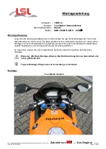
–Tour-Match Kit Fitting Instructions 


1.)  To avoid scratches and dents and for re-routing of hoses and cables remove gas tank first. 

Remove  fairing  bracket  and  mirrors  if  necessary. 

Always  disconnect  battery  ground 

before working on electric wiring and switches!


2.)  Remove  handlebar  controls,  clutch  lever  bracket and  brake  cylinder  assy,  then  original 

handlebar. 

3.)  To assemble the Tour-Match clamps the original top yoke must be dismantled. To ensure 

a stress-free disassembly and assembly of the triple clamp, the front wheel must be re-
lieved.  Slide the Tour-Match clamps on the fork legs. The Tour-Match clamps are assem-
bled only suitable for transport and must now be tightened. Please tighten the M6 bolts to 
10 Nm of torque. This process must be repeated alternately, as at tightening the second 
screw each other is released again. When installing the fork bridge make sure to tighten 
that  first  attracted  the  central  control  head  nut  with  approximately  15Nm  and  then  the 
clamping screw. Thereafter, the control head nut and all fittings according to the manufac-
turer tighten to the prescribed torque. 


Do not use any grease / oil at the the bolts!


4.)  Remove brake line. 

Caution: avoid brake fluid on painted surfaces!

 Mount enclosed 

brake line with new gaskets. Read the separate brake line fitting instructions. 

Caution: Any work on brake system or bleeding the system should be done by au-
thorized  dealer  or  qualified  mechanic!  Pump  brake  lever  until  proper  pressure  is 
built up on lever. Test brakes at low speed!


5.)  Now mount handlebar controls and clutch/brake assy. Set drillings to fix controls on han-

dlebars. Re-route cables and hoses if necessary. Make sure that no cable is bended and 
move tensions free. Fix the left grip rubber with suitable glue. 

6.)  Shorten fairing to allow full steering movement of handlebar with proper space at levers 

and  switches.  Check  throttle  and  clutch  cables function  and  clearance  on  both  left  and 
right steering angles. Adjust or re-route if necessary. A few bikes need a limitation of the 
steering stop. There for you have to fix the lock stop shims with special adhesive on the 
original steering stop.  

7.)  Always check local laws and your manufacturers warranty conditions for using aftermarket 

parts on your bike! 


Ride safe and have fun! 


Summary of Contents for 150H131

Page 1: ...durch wenn Sie daf r qualifiziert sind andernfalls empfehlen wir dringend die Montage in einer Fachwerkstatt Ein fehlerhafter Anbau kann das Fahrverhalten des Motorrades negativ beeinflussen und Ihre...

Page 2: ...mit der Gabelbr cke ber die Standrohre schieben entfernen Sie die Sicherungsringe auf den Standrohren Bei der Montage der Gabelbr cke ist darauf zu achten dass zuerst die zentrale Steuerkopfmutter mi...

Page 3: ...20Nm fest Entl ften der Bremsleitung Dr cken Sie die Bremsbel ge wieder zur ck bis Sie die Bremss ttel wieder ber die Bremsscheiben schieben k nnen Montieren Sie die Bremss ttel wieder nach Hestellerv...

Page 4: ...Montagefett l eingesetzt werden 4 Wenn neue Bremsleitungen im Lieferumfang enthalten sind wie folgend vorgehen Bremshydraulikleitung abbauen Vorsicht Bremsfl ssigkeit darf nicht auf Lackteile tropfen...

Page 5: ...ork only if you re qualified otherwise we recommend this mounting to be done by a qualified workshop Improperly mounting of this kit can reduce the driveability of the motorcycle and may be a risk to...

Page 6: ...fix top yoke first tighten steering head nut up to 15Nm 11lbf ft then fix the slider tube clamp bolts Now tighten steering head up to the required torque tightening torques refer to the vehicle manuf...

Page 7: ...s and tighten the double banjo bolt M10x1 25 with 17 20 Nm Bleeding the Brake Line Push back the brake pads until you are able to put the calipers back on the brake discs Install the brake calipers ba...

Page 8: ...the control head nut and all fittings according to the manufac turer tighten to the prescribed torque Do not use any grease oil at the the bolts 4 Remove brake line Caution avoid brake fluid on paint...

Page 9: ...ives de s curit Si vous n tes pas m canicien nous vous recommandons le montage dans un atelier sp cialis Le montage incorrect peut influencer la conduite de mani re n gative et mettre en danger votre...

Page 10: ...Supprimez les circlips sur les bras de fourche avant d y passer les colliers Tour Match avec le t de fourche Pendant le montage du t de fourche serrez d abord l crou central un couple de serrage de 1...

Page 11: ...creuse double du kit Utilisez absolument de nouveaux joints 3 pi ces et serrez la vis creuse M10x1 25 un couple de 17 20Nm Purge de la durit Poussez les plaquettes jusqu pouvoir enfiler les triers par...

Page 12: ...cas ou la durite de frein est remplac e proc dez de la mani re suivante D montez la durite de frein Attention Le liquide de frein ne doit pas tomber sur les parties peintes Montez la durite de remplac...

Reviews: