


3. Wiring
3-1
3. Wiring
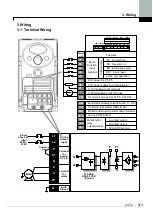
3.1 Terminal Wiring
L1
L2
P
P1
N
U
V
W
Single
phase AC
input
200V ~
230V
AC line
voltage
input
Terminal
for
Inverter
DC P/S
Terminal
for
motor
Common
bar
L1
L2
P
P1
N
U
V
W
CLASS B
EMI FILTER
(Option)
Motor
G
Earth
Ground
P1
P2
P3
P4
P5
CM
P24
VR
V1
I
MO
30A
30B
30C
Termi-
nal
Features
Multi-
Function
input
terminal
Common Terminal for P1-P5, AM, P24
24V power for P1-P5
In
it
ia
l s
e
tt
in
g
FX : Forward run
RX : Reverse run
BX : Emergency stop
JOG : Jog operation
RST : Fault reset
12V power supply for potentiometer
0-10V Analog Input terminal
0-20mA Analog Input terminal
AM
Multi-function Analog output terminal ( 0 ~ 10V)
CM
Common terminal for AM terminal
EXTG
Multi-function open collector output terminal
Ground T/M for MO
A contact output
B contact output
30A 30B Common
Multi-function
relay
output terminal
30A 30B 30C
MO EXTG P24 P1 P2 CM P3
P4 P5 VR V1 CM I AM
Summary of Contents for SV004iC5-1F
Page 8: ......
Page 22: ...3 Wiring 3 6 ...
Page 38: ...5 Programming Keypad 5 14 ...
Page 42: ...6 Basic Operation 6 4 ...
Page 64: ...7 Function List 7 22 ...
Page 74: ...9 Specifications 9 4 ...


