background image

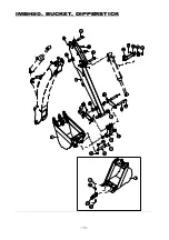
IMBH50. BUCKET, DIPPERSTICK

NO.

PART NO.

DESCRIPTION

Q'TY I.C.

SERIAL OR DATE

40231071

BUCKET ASS'Y(9)

1

40394246

BUCKET W.A(9)

1

2018.09.05~

40231072

BUCKET ASS'Y(12)

1

40394247

BUCKET W.A(12)

1

2018.09.05~

40231073

BUCKET ASS'Y(16)

1

40394248

BUCKET W.A(16)

1

2018.09.05~

40231074

BUCKET ASS'Y(18)

1

40394249

BUCKET W.A(18)

1

2018.09.05~

40231075

BUCKET ASS'Y(24)

1

40394250

BUCKET W.A(24)

1

2018.09.05~

40231076

BUCKET ASS'Y(36)

1

40394251

BUCKET W.A(36)

1

2018.09.05~

2

40231058

DIPPERSTICK ASS'Y

1

3

40231079

LINK ASS'Y

1

40400865

LINK ASS'Y

1

2018.11.01~

4

40231078

LINK-RH

1

40400867

LINK-RH

1

2018.11.01~

5

40231077

LINK-LH

1

40400866

LINK-LH

1

2018.11.01~

6

40231094

PIN,

30-195.5L

2

8

40231092

PIN,

30-154.5L

2

9

40256377

HEX.BOLT,M8-1.25P 60L

4

10

40230896

NUT-SELFLOCK,M8-1.25P

4

11

40228707

NIPPLE,GREASE,1/8"

4

13

40231037

SOCKET BRACKET

1

14

40231036

SOCKET

1

15

40228698

CABLE TIE,540mm BLACK

2

16

40256356

HEX.BOLT, M8-1.25P 20L

2

17

40228629

HEX.NUT,M8-1.25P

2

18

40230979

BUSHING,404440

2

19

40230978

BUSHING,303440

2

20

40230907

BUSHING,252830

4

21

40231097

PIN,

25-195.5L

2

22

40230884

HEX.BOLT,M10-1.5P 60L

2

23

40228634

NUT-SELFLOCK,M10-1.5P

2

1

- 71 -

Summary of Contents for I3030

Page 1: ...20 R4020H XR3032 XR3032H XR3037 XR3037H XR4040 XR4040H XR4046 XR4046H XR3135 XR3135H XR3140 XR3140H XR4140 XR4140H XR4145 XR4145H XR4150 XR4150H XR4155 XR4155H MT342 MT347 MT352 MT357 MT345E MT350E MT355E R MANUAL MT345E MT350E MT355E L PO Box 70 Battleboro NC 27809 Tel 252 984 0700 LB2 Tel 252 984 0700 Fax 252 984 0701 www lstractor com www lstractorusa com 2100 P NO BT014 ME000 REVISION 24 ...

Page 2: ... XR3037 XR3037H XR4040 XR4040H XR4046 XR4046H XR3135 XR3135H XR3140 XR3140H XR4140 XR4140H XR4145 XR4145H XR4150 XR4150H XR4155 XR4155H MT342 MT347 MT352 MT357 MT345E MT350E MT355E ㆍTHUMB 40394273 Model LB2100 LS BACKHOE OPERATOR MANUAL Applied Tractor Backhoe Option ...

Page 3: ... period of 1 year from the date of the original retail sale Parts replaced or repaired under the terms of this Warranty are guaranteed only until the original warranty expires Warranty only applies to the original purchaser It is further understood and agreed that the defect should be immediately reported to the Selling Dealer The Selling Dealer will generally perform Warranty repairs or replaceme...

Page 4: ...ipment review this manual and all safety messages contained within This safety symbol indicates important safety messages in this manual When you see this symbol carefully read the message that follows and be alert to the possibility of personal injury or death 3 ...

Page 5: ...arts IIlustrations 45 General Information 45 IMBH10 Subframe I3030 I3030H I3040 I3040H 46 XR3032 XR3032H XR3037 XR3037H 48 R4010 R4010H R4020 R4020H 50 XR3135 XR3135H XR3140 XR3140H XR3135 XR3140 52 XR4040 XR4040H XR4046 XR4046H 56 XR4140 XR4145 XR4150 XR4155 MT342 MT347 MT352 MT357 58 MT345E MT350E MT355E 60 IMBH20 Main Frame 62 IMBH21 Seat Control WALVOIL 64 IMBH30 Swing Frame 66 IMBH40 Boom 68 ...

Page 6: ...357 78 MT345E MT350E MT355E 80 IMBH62 Hydraulic Control Fitting WALVOIL 86 IMBH70 Bucket Cylinder 90 IMBH71 Dipperstick Cylinder 92 IMBH72 Boom Cylinder 94 IMBH73 Swing Cylinder 96 IMBH74 Stabilizer Cylinder LH 98 IMBH74 Stabilizer Cylinder RH 100 IMG980 Decals 102 5 ...

Page 7: ... see this symbol carefully read the message that follows and be alert to the possibility of personal injury or death SAFETY PRECAUTIONS DANGER Indicates an imminently hazardous situation that if not avoided will result in DEATH or serious INJURY A frequent cause of personal injury or death is persons falling off and being run over Do not permit others to ride on your tractor Only one person the op...

Page 8: ...ing damaged or injuring someone When using a backhoe be alert of bucket boom and dipper stick arm position at all times CHILDREN SAFETY It may result tragic accidents if the operator works without aware of presence of children Children are generally well attracted to machines and their work Operator should pay attention to children s moving while working or driving the machine Stop the machine imm...

Page 9: ...n on public streets or highways before transporting or traveling the machine Install SMV emblem as required SMV Slow Moving Vehicle Pull up the boom completely and position in center Close the dipperstick completely and curl the bucket completely Engage the boom and swing locks before driving the tractor Boom Lock Swing Lock SMV emblem 8 ...

Page 10: ...ying on a clean dry surface and pressing air bubbles to outside edges Care of Safety Decals 1 Keep safety decals clean and free of obstructing material 2 Clean safety decals with soap and water and dry with a soft cloth Warning decals are visible when getting on backhoe Refer to the left and right hands used in this manual It s the position of the operator when seated in the operating position of ...

Page 11: ...SAFETY DECALS 40451025 40358872 40358873 40358868 40358870 40358871 10 ...

Page 12: ...SAFETY DECALS 40358874 40358875 40358878 40450477 40358876 40358812 40455586 11 ...

Page 13: ...hout bucket 485 1 069 lbs Bucket Digging Force 1 215 2 679 lbs Dipperstick Digging Force 955 2 105 lbs Operating Pressure 170 bar 2 466 psi Specifications may vary depending on tractor model tire size and bucket used Specifications and design are subject to change without prior mm inch mm inch mm inch mm inch Boom 70 2 756 620 24 409 384 15 118 40 1 575 Bucket 60 2 362 535 21 063 299 11 772 35 1 3...

Page 14: ... I 1727 4 lbs 3780 7 3800 2 kg kg F 1688 1 lbs G 1702 2 lbs 3713 9 3744 9 kg kg D 1666 6 lbs E 1677 5 lbs 3666 5 3690 5 kg kg B 1694 8 lbs C 1676 0 lbs 3728 5 3687 2 kg kg Rated Lift Capacities A 1713 9 lbs 3770 7 kg FEET 0 2 4 6 8 10 METERS 0 0 5 1 0 1 5 2 0 2 5 3 0 8 6 4 2 0 2 4 6 10 12 8 0 0 5 1 0 1 5 2 0 2 5 0 5 1 0 1 5 2 0 2 5 3 0 3 5 13 ...

Page 15: ...ivery and Registration form and also below for your reference The purpose of this manual is to assist you in maintaining and operating your backhoe Read it carefully it furnishes information and instructions that will help you achieve years of dependable performance Some information may be general in nature due to unknown and varying conditions However through experience and these instructions you...

Page 16: ...lication significantly increase demands on the tractor Hydraulic System Check the tractor Hydraulic system fluid level daily Refer to your tractor Operator s Manual maintenance section for instructions regarding tractor hydraulic system maintenance The tractor must be equipped with an approved ROPS system to ensure adequate operator s protection Important Never add liquid ballast or any other weig...

Page 17: ...the mainframe to drop suddenly causing damage to the tractor or backhoe or injury to personnel Before operating the backhoe fully raise and lower the boom dipperstick arm swing and stabilizers two or three times Then raise the bucket above the ground and cycle the bucket cylinders three times Lower the bucket to the ground Check the tractor hydraulic oil and the correct oil level Check tractor wit...

Page 18: ...ace all controls in neutral and either set the parking brake or place tractor in park as equipped Always keep cylinders in a retracted position when the backhoe is not in use to guard against rust and contamination which may cause damage to the cylinder rods or hydraulic system Operate controls only when seated in the operator s seat For smooth operation in cold weather let the tractor warm up Slo...

Page 19: ...drift up or down without pressure Boom and Swing Controls Do not dig near the stabilizers to avoid possible accident Move the left hand outer control lever to the left boom swings to the left Move lever right backhoe boom swing moves to the right Push the left right hand inner control lever left right stabilizer goes down Left and Right Stabilizer Controls Pull the left right hand inner control le...

Page 20: ...n and increase operating efficiency Digging Safety Never leave from the backhoe seat while operating the backhoe Lower the stabilizers and loader bucket to ground before operating backhoe Check carefully for buried electric cables or gas water pipes before digging Important Do not use the machine to pull out tree stumps with the boom dipper completely extended and the bucket crowded position Bucke...

Page 21: ... to work area Piles of Spoil If there are teeth in the bucket remove them before digging vertical walls Extend the boom slowly while lowering the bucket to the far vertical wall Dump the bucket until the bottom of the bucket be always in a vertical position Digging Vertical Walls Crowd out the far wall while forcing the bucket down with the boom Raise the boom to finish the near wall while crowdin...

Page 22: ... and swing locks while driving or using loader Transporting Before transporting the machine position boom straight back and engage the boom lock lever in boom Swing backhoe to position in the middle of swing and drop the pin through holes in swing frame When not in use pull back boom lock lever and store pin in hole provided on swing frame Boom Lock Swing Lock Stabilizer Lock 21 ...

Page 23: ...damage other objects Do not dig near stabilizers Ground under stabilizers could collapse Make all movements slow and gradual when practicing operation Make sure always fasten the machine with chains and chain binders to the trailer Determine and note the maximum height of the machine for underpass clearance before transporting Note Use strong and long enough ramps to provide a low angle to the tra...

Page 24: ...e Before starting the engine of your tractor make sure all operating controls are in park lock or neutral position Operate controls only when seated in the operator s seat Never allow any part of body under the machine and between tractor and backhoe Before leaving the backhoe operator s seat fully lower the boom to the ground STEP 1 Move the tractor to backhoe storage place STEP 3 Center the boom...

Page 25: ...or forward slowly until the backhoe subframe disengages of the mounting brackets Important Be careful not to damage or break the hydraulic hoses when moving the tractor STEP 5 STEP 4 Using the control levers position the dipperstick vertically curl the bucket until its bottom is level with the ground and lower the boom until bottom of the bucket rests on the ground STEP 8 Lower the backhoe mainfra...

Page 26: ...on after remove the backhoe The hydraulic oil is dangerous for skin or eyes Wash the skin and seek medical service if it is necessary STEP 10 Start the engine then drive tractor slowly away from the disconnected backhoe Be sure that there is sufficient ballast weight in the rear tires or an implement is attached to the 3 point hitch before using the loader without backhoe Be careful to avoid injur...

Page 27: ...ny part of body under the machine and between tractor and backhoe Remove 3 point hitch and drawbar if installed Connect the backhoe hydraulic couplers to the tractor couplers Make sure white cap is backhoe IN line and black cap is backhoe OUT line Connect couplers in the same color Restart the engine and stand beside the rear tire to possible to control the backhoe control levers STEP 5 Lower the ...

Page 28: ... pins to the lock pins If no return to STEP 6 STEP 9 Raise the stabilizers and boom Engage the boom lock and stabilizer lock bars STEP 10 Move the machine to an open area and cycle all backhoe functions This will check their operation and flow oil back through the system filtering it and refilling each circuit Check the hydraulic oil level before putting the backhoe into full operation Grease at a...

Page 29: ...TEP 1 SMV bracket Hardware STEP 2 SMV Sign Remove SMV sign from rear of the tractor This SMV sign should re install to the Remove Hardware and SMV bracket before install the backhoe If SMV bracket not removed it will interference with backhoe 28 ...

Page 30: ...CKHOE INSTALLATION Seat plate Hardware STEP 3 Assembl the Seat and Seat plate with packed hardware as shown in drawing Seat If the seat not assembled at A and B holes it will interference with tractor 29 ...

Page 31: ... Line Bolt Nut Washer spring Tire LH STEP 1 Remove the bolts from the tractor RInstall the dust plug to the quick coupler Install the plate to the tractor with bolts RWind up the teflon tape on the nipple and tighten the quick coupler to the nipple Install the nipple to the plate with nut as shown in above figure and tighten these nut and nipple Remove the hardware and tire from the tractor 30 ...

Page 32: ...STEP 4 STEP 5 Install the hydraulic hose to the hydraulic housing of the tractor with union bolt and bonded seals Remove the union bolts and pipe from the tractor It is easy to install and disassemble the backhoe hydraulic parts if remove the joystick cable and nut first Wind up the teflon tape on the nipple and tighten this nipple to the hydraulic hose Install the hydraulic hose to the tractor co...

Page 33: ...3 STEP 4 Install the quick coupler and dust cap to the nipple Tighten the quick coupler Remove the Plug and bolt from the tractor Wind up the teflon tape on the tap of T line pipe and tighten the quick coupler to the pipe Install the dust plug to the quick coupler Install the pipe assembly with Union bolt and bonded seals to the hydraulic housing of the tractor And tighten the bolt 32 ...

Page 34: ...khoe Hydraulic STEP 1 Hydraulic Line Connect the Backhoe hydraulic hoses P and T as shown in drawing Loader only Connect B to C Loader and Backhoe Disconnect B from C and make free hose B Connect backhoe P to C and connect backhoe T to D 33 ...

Page 35: ...den line burst could cause the boom dipperstick arm or bucket to drop suddenly causing damage to the tractor or backhoe or injury to personnel Escaping fluid under pressure can have sufficient force to penetrate the skin causing serious injury Operate the backhoe from the operator seat only Do not stand or walk under a raised backhoe Accidental movement of control lever or leak in hydraulic system...

Page 36: ... system Check the hydraulic level of tractor daily before operating the machine Replenish the oil as described in the tractor operator s manual Lubricate at all grease nipple of pivot pins as refer to Lubrication Quick Figure Check cylinder rod packings If there is seepage service as needed Check all hydraulic lines hoses and connections If there is leak or damage replace or service as needed Chec...

Page 37: ... hardware are loosened retighten to specified torque Check all hardware frequently and keep them tight Check sub frame hardware regularly especially when new If they are loosen tighten them as belows To avoid personal injury Weekly or Every 50 Hours Checks No Bolt and nut 1 2 3 4 5 M20 457 N m 337 lbs ft 6 M22 623 N m 460 lbs ft Tightening torque M14 151 N m 111 lbs ft 36 ...

Page 38: ...ardware Lubricate Check for leaks wear Check for seepage service as needed Daily 10 hours Boom Dipperstick Swing and Bucket cylinder rod packings Check replace if necessary Check replace if m issing As specified in Tractor Operator s Manual Tire Inflation Weekly 50 hours Daily 10 hours Check Check As specified in Tractor Operator s Manual Hydraulic SystemOil Level Hydraulic SystemOil Level Replace...

Page 39: ... even though they are heat treated The digging force weakens as the teeth wear out Remove the worn teeth and install new teeth if the teeth are worn Install a new bucket or other implement as the type of job to be accomplished Note Make sure to use brass drift and hammer when removing hinge pins Failure to do so could result in injury from flying metal fragments Backhoe Bucket Changing As the work...

Page 40: ...lic oil Inspect for blockage Disassemble valve if necessary Check system pressure Repair or replace pump Hydraulic hose or tubeline blockage Check for evidence of damage to hoses or tubelines that would block flow of oil between cylinders and control valve Inspect Repair as required Quick disconnect coupler s are not fully connected or Flow Check Check coupler connections Replace coupler s if nece...

Page 41: ...ng internally hypassing fluid within valve Replace control valve and recheck operation Hydraulic hose or tubeline restriction hoses tubline kinked or pinched Check hoses and tubelines for evidence of restriction Boom Dipperstick or Bucket cylinder piston assembly leakage Check cylinders for leakage Repair as needed Aeration of hydraulic fluid Refer to Aeration of Hydraulic Fluid Quick disconnect c...

Page 42: ... centering spring Check cylinders for leakage Control valve internal leakage Note A gradual drop over an extended period of time is a normal condition Replace control valve and recheck System relief valve squeals Backhoe drops with control valve spool in centered position no external oil leakage evident Cylinder piston assembly leakage Control valve spool binding in valve body spool bore Relief va...

Page 43: ...ic pump defective Excessive shock load on lift cylinders during transport Replace defective parts Review and observe proper and safe operational practices Refer to Tractor Operator s Manual for service recommendations Hydraulic hose restriction Check for evidence of restriction in hydraulic hoses Cold hydraulic fluid Allow hydraulic fluid to warm up to operating temperature Engine R P M too slow I...

Page 44: ...HYDRAULIC SYSTEM SCHEMATIC Boom Cylinder Swing Cylinders Left Stabilizer Cylinder Dipperstick Cylinder Bucket Cylinder Right Stabilizer Cylinder Tractor or Pump Kit 43 ...

Page 45: ... 18mm 68 50 94 70 75 55 103 76 12 x 1 25 14 x 2 0 21mm 109 80 151 111 116 87 163 120 14 x 1 5 16 x 2 0 24mm 169 125 234 173 181 133 250 184 16 x 1 5 18 x 2 5 27mm 234 172 323 239 263 194 363 268 18 x 1 5 20 x 2 5 30mm 330 244 457 337 367 270 507 374 20 x 1 5 22 x 2 5 34mm 451 332 623 460 495 365 684 505 22 x 1 5 24 x 3 0 36mm 571 421 790 583 623 459 861 635 24 x 2 0 30 x 3 0 46mm 1175 867 1626 119...

Page 46: ... Indicates that either parts can not be used Interchanged serial number or date Indicates the interchangeability of parts due to design change The individual parts in their normal relationship to each other Reference numbers are used in the illustrations These numbers correspond to those in the Number column and are followed by the quantity required and description Right hand and Left hand sides a...

Page 47: ...IMBH10 SUBFRAME I3030 I3030H I3040 I3040H 46 ...

Page 48: ... 40230905 PIN 2 6 40228656 RING PIN 10 2 7 40228623 HEX BOLT HT M14 2 0P 60L 4 8 40230601 HEX BOLT HT M14 2 0P 40L 4 40264168 HEX BOLT HT M14 2 0P 50L 4 2019 08 08 9 40230894 HEX BOLT HT M20 2 5P 70L 4 10 40230895 HEX BOLT HT M22 2 5P 70L 4 11 40230893 HEX BOLT HT M14 2 0P 55L 2 2011 02 22 12 40264330 SPACER 1 2012 05 08 14 40228643 WASHER SPRING M14 8 40228643 WASHER SPRING M14 10 2011 02 22 15 4...

Page 49: ...IMBH10 SUBFRAME XR3032 XR3032H XR3037 XR3037H 48 ...

Page 50: ...LT HT M14 2 0P 50L 4 2019 08 08 9 40230894 HEX BOLT HT M20 2 5P 70L 4 40343000 HEX BOLT HT M20 2 5P 80L 2 2016 03 15 10 40230895 HEX BOLT HT M22 2 5P 70L 4 40343501 HEX BOLT HT M22 2 5P 80L 4 2016 03 15 11 40228643 WASHER SPRING M14 10 12 40228645 WASHER SPRING M20 4 13 40230899 WASHER SPRING M22 4 14 40228637 HEX NUT HT M14 2 0P 4 15 40228639 HEX NUT HT M20 2 5P 4 16 40230898 HEX NUT HT M22 2 5P ...

Page 51: ...IMBH10 SUBFRAME R4010 R4010H R4020 R4020H 50 ...

Page 52: ... RING PIN 2 8 40228623 HEX BOLT HT M14 2 0P 60L 4 9 40230894 HEX BOLT HT M20 2 5P 70L 4 10 40230895 HEX BOLT HT M22 2 5P 70L 4 11 40230601 HEX BOLT HT M14 2 0P 40L 2 2011 03 21 14 40228643 WASHER SPRING M14 4 40228643 WASHER SPRING M14 6 2011 03 21 15 40228645 WASHER SPRING M20 4 16 40230899 WASHER SPRING M22 4 21 40228637 HEX NUT HT M14 2 0P 4 22 40228639 HEX NUT HT M20 2 5P 4 23 40230898 HEX NUT...

Page 53: ...IMBH10 SUBFRAME XR3135 XR3135H XR3140 XR3140H 52 ...

Page 54: ...LT HT M14 2 0P 50L 4 2016 03 15 9 40230894 HEX BOLT HT M20 2 5P 70L 4 40343000 HEX BOLT HT M20 2 5P 80L 4 2016 03 15 10 40230895 HEX BOLT HT M22 2 5P 70L 4 40343501 HEX BOLT HT M22 2 5P 80L 4 2016 03 15 11 40228643 WASHER SPRING M14 10 12 40228645 WASHER SPRING M20 4 13 40230899 WASHER SPRING M22 4 14 40228637 HEX NUT HT M14 2 0P 4 15 40228639 HEX NUT HT M20 2 5P 4 16 40230898 HEX NUT HT M22 2 5P ...

Page 55: ...IMBH10 SUBFRAME XR3135 XR3135H XR3140 XR3140H 54 ...

Page 56: ... 40264168 HEX BOLT HT M14 2 0P 50L 4 2019 08 08 8 40230893 HEX BOLT HT M14 2 0P 55L 2 9 40343000 HEX BOLT HT M20 2 5P 80L 2 10 40343504 HEX BOLT HT M20 2 5P 90L 2 11 40343501 HEX BOLT HT M22 2 5P 80L 4 12 40228643 WASHER SPRING M14 6 13 40228645 WASHER SPRING M20 4 14 40230899 WASHER SPRING M22 4 15 40228639 HEX NUT HT M20 2 5P 4 16 40230898 HEX NUT HT M22 2 5P 4 17 40343502 NUT SELFLOCK M20 2 5P ...

Page 57: ...IMBH10 SUBFRAME XR4040 XR4040H XR4046 XR4046H 56 ...

Page 58: ...HEX BOLT HT M20 2 5P 70L 4 40343000 HEX BOLT HT M20 2 5P 80L 2 2016 03 15 10 40230895 HEX BOLT HT M22 2 5P 70L 4 40343501 HEX BOLT HT M22 2 5P 80L 4 2016 03 15 11 40230601 HEX BOLT HT M14 2 0P 40L 2 12 40343504 HEX BOLT HT M20 2 5P 90L 2 2016 03 15 14 40228643 WASHER SPRING M14 6 15 40228645 WASHER SPRING M20 4 16 40230899 WASHER SPRING M22 4 21 40228637 HEX NUT HT M14 2 0P 4 22 40228639 HEX NUT H...

Page 59: ...IMBH10 SUBFRAME XR4140 XR4145 XR4150 XR4155 MT342 MT347 MT352 MT357 58 ...

Page 60: ...00 HEX BOLT HT M20 2 5P 80L 2 2016 03 15 10 40230895 HEX BOLT HT M22 2 5P 70L 4 40343501 HEX BOLT HT M22 2 5P 80L 4 2016 03 15 11 40230601 HEX BOLT HT M14 2 0P 40L 2 12 40343504 HEX BOLT HT M20 2 5P 90L 2 2016 03 15 14 40228643 WASHER SPRING M14 6 15 40228645 WASHER SPRING M20 4 16 40230899 WASHER SPRING M22 4 21 40228637 HEX NUT HT M14 2 0P 4 22 40228639 HEX NUT HT M20 2 5P 4 23 40230898 HEX NUT ...

Page 61: ...IMBH10 SUBFRAME MT345E MT350E MT355E 60 ...

Page 62: ...40228656 RING PIN 2 7 40230601 HEX BOLT HT M14 2 0P 40L 2 8 40343000 HEX BOLT HT M20 2 5P 80L 2 9 40343504 HEX BOLT HT M20 2 5P 90L 2 10 40343501 HEX BOLT HT M22 2 5P 80L 4 11 40228643 WASHER SPRING M14 2 12 40228645 WASHER SPRING M20 4 13 40230899 WASHER SPRING M22 4 14 40228639 HEX NUT HT M20 2 5P 4 15 40230898 HEX NUT HT M22 2 5P 4 16 40343502 NUT SELFLOCK M20 2 5P 4 17 40343503 NUT SELFLOCK M2...

Page 63: ...IMBH20 MAIN FRAME 62 ...

Page 64: ...5 175L 2 12 40231104 STABILIZER LOCK 2 13 40231105 WASHER 2 14 40261484 HEX BOLT M10 1 5P 90L 2 15 40228641 WASHER SPRING M10 2 16 40230877 RUBBER STOP 2 17 40231035 U BOLT 40 5 16 18 1 18 40261479 HEX BOLT M8 1 25P 50L 8 19 40230896 NUT SELFLOCK M8 1 25P 8 20 40228634 NUT SELFLOCK M10 1 5P 4 21 40230901 HEX NUT 5 16 4 22 40230888 HEX BOLT M16 2 0P 60L 4 23 40228644 WASHER SPRING M16 4 24 40228636...

Page 65: ...IMBH21 SEAT CONTROL WALVOIL 64 ...

Page 66: ... BOLT SEM S M8 1 25P 40L 4 16 40294005 BOOT LEVER ASS Y 2 40343509 BOOT LEVER ASS Y 2 2016 03 15 40369943 BOOT LEVER ASS Y 2 2017 05 11 17 40294006 HAND LEVER 2 40343510 HAND LEVER 2 2016 03 15 18 40231103 SWING PIN 1 19 40230882 HEX BOLT M10 1 5P 40L 1 40432634 HEX BOLT M10 1 5P 20L 1 2020 03 24 20 40231081 SUPPORT SEAT 1 21 40256413 PLATE SEAT 1 22 40231138 SEAT 1 40373768 SEAT 1 2017 08 05 23 4...

Page 67: ...IMBH30 SWING FRAME 66 ...

Page 68: ...ANDLE SET 1 40343507 HANDLE SET 1 2016 03 15 7 40231031 PLASTIC BALL 1 8 40231102 LOCK 1 9 40230946 SNAP RING C22 2 10 40231055 SPRING 1 11 40261806 PIN 1 12 40228634 NUT SELFLOCK M10 1 5P 1 13 40230896 NUT SELFLOCK M8 1 25P 6 14 40256377 HEX BOLT M8 1 25P 60L 3 15 40294062 HEX BOLT M8 1 25P 50L 2 16 40230878 HEX BOLT M8 1 25P 25L 1 17 40230879 HEX BOLT M8 1 25P 35L 1 18 40229894 HEX BOLT M10 1 5P...

Page 69: ...IMBH40 BOOM 68 ...

Page 70: ...31057 BOOM ASS Y 1 2 40231095 PIN 30 176 5L 1 3 40231096 PIN 40 185 5L 1 4 40231093 PIN 40 185 5L 1 5 40256377 HEX BOLT M8 1 25P 60L 1 6 40294063 HEX BOLT M8 1 25P 70L 2 7 40230896 NUT SELFLOCK M8 1 25P 3 8 40228707 NIPPLE GREASE 1 8 1 9 40230979 BUSHING 404440 2 69 ...

Page 71: ...IMBH50 BUCKET DIPPERSTICK 70 ...

Page 72: ...CK ASS Y 1 3 40231079 LINK ASS Y 1 40400865 LINK ASS Y 1 2018 11 01 4 40231078 LINK RH 1 40400867 LINK RH 1 2018 11 01 5 40231077 LINK LH 1 40400866 LINK LH 1 2018 11 01 6 40231094 PIN 30 195 5L 2 8 40231092 PIN 30 154 5L 2 9 40256377 HEX BOLT M8 1 25P 60L 4 10 40230896 NUT SELFLOCK M8 1 25P 4 11 40228707 NIPPLE GREASE 1 8 4 13 40231037 SOCKET BRACKET 1 14 40231036 SOCKET 1 15 40228698 CABLE TIE 5...

Page 73: ...IMBH50 BUCKET DIPPERSTICK 72 ...

Page 74: ... 9 3 TOOTH BOLT TYPE 12 3 TOOTH BOLT TYPE 16 4 TOOTH BOLT TYPE 18 4 TOOTH BOLT TYPE 24 5 TOOTH BOLT TYPE 36 6 25 40394259 FLAT HEADED BOLT HT WRENCH M12 1 75P 50L 2 Q ty Per Tooth 26 40228642 WASHER SPRING M12 2 Q ty Per Tooth 27 40230897 HEX NUT HT M12 1 75P 2 Q ty Per Tooth 24 40394258 73 ...

Page 75: ...IMBH60 CONTROL VALVE SD6 6 74 ...

Page 76: ...FE SD6 SAE10 1 43 40307880 SPOOL 5BY 13QN SD6 1 44 40307879 SPOOL 1 SD6 5 54 40307896 PLUG TCEI SAE 10 2 63 40324627 GASKET 2 64 40324628 END CAP KIT 1 65 40324629 TIE ROD KIT SD6 6 1 66 40324630 LCN KIT 2 TYPE 3 TYPE 1 67 40324631 MRV 1 68 40324632 CONTROL KIT 1 69 40324633 LEVER KIT 1 70 40324634 FIANCATA FS SD6 RD SAE10 1 71 40324635 KIT ELEMENT SD6 QH SAE8 3 72 40324636 KIT ELEMENTO SD6 P SAE8...

Page 77: ...IMBH61 HYDRAULIC LINE I3030 I3030H I3040 I3040H R4010 R4010H R4020 R4020H BACKHOE IN BACKHOE OUT 76 ...

Page 78: ...ST CAP 3 8 WHITE FEMALE 2 5 40228720 QUICK COUPLER PT3 8 MALE 2 6 40230961 NIPPLE PF1 2 O RING PT3 8 1 7 40228757 O RING 1BP18 1 8 40230975 HOSE ASS Y 4 3 4 16UNF 1 PT1 2 1700L 3 8 2 9 40230968 QUICK COUPLER PT1 2 FEMALE 2 10 40230970 DUST PLUG 1 2 WHITE MALE 1 11 40228715 NIPPLE PT3 8 3 4 16UNF HOSE 90 3 12 40230969 DUST PLUG 1 2 BLACK MALE 1 13 40228698 CABLE TIE 540mm BLACK 5 40228758 TEFRON TA...

Page 79: ...IMBH61 HYDRAULIC LINE XR4140 XR4145 XR4150 XR4155 MT342 MT347 MT352 MT357 78 ...

Page 80: ...RAULIC LINE NO PART NO DESCRIPTION Q TY I C SERIAL OR DATE 1 40286936 WASHER COPPER M20 1 2 40286939 NIPPLE M20 1 5P COPPER PT1 2 1 3 40230968 QUICK COUPLER PT1 2 FEMALE 1 4 40230969 DUST PLUG 1 2 BLACK MALE 1 79 ...

Page 81: ...IMBH61 HYDRAULIC LINE MT345E MT350E MT355E S N 181129640 80 ...

Page 82: ...PART NO DESCRIPTION Q TY I C SERIAL OR DATE 1 40228731 NIPPLE PF3 8 1 2 40228654 BONDED SEAL 3 8 2 3 40375341 T LINE PIPE 1 4 40230968 QUCIK COUPLER PT1 2 FEMALE 1 5 40230969 DUST PLUG 1 2 MALE BLACK 1 40228758 TEFLON TAPE 1 81 ...

Page 83: ...IMBH61 HYDRAULIC LINE MT345E MT350E MT355E S N 200415068 82 ...

Page 84: ...T1 2 FEMALE 2 7 40401016 DUST PLUG 1 2 MALE RED 1 8 40404034 VALVE BRACKET 1 9 40230890 SEM S BOLT M8 1 25P 40L 2 10 40228629 NUT M8 1 25P 2 11 40400884 BENZO BOLT PF1 2 1 12 40400880 HOSE 4 3 4 16UNF x BENZO PF1 2 2280L 3 8 1 13 40400881 HOSE 4 3 4 16UNF x BENZO PF3 8 1500L 3 8 1 14 40228731 BENZO BOLT PF3 8 2 15 40228654 BONDED SEAL 3 8 4 16 40375341 T LINE PIPE PF3 8 x PT1 2 1 17 40230970 DUST ...

Page 85: ...IMBH61 HYDRAULIC LINE MT345E MT350E MT355E 84 ...

Page 86: ...6 40400884 BENZO BOLT PF1 2 1 7 40228653 BONDED SEAL 1 2 2 8 40434304 HOSE 4 3 4 16UNF x BENZO PF3 8 1050L 3 8 1 9 40228731 BENZO BOLT PF3 8 2 10 40228654 BONDED SEAL 3 8 4 11 40434305 NIPPLE PT1 2 x 3 4 16UNF HOSE 90 1 12 40230967 QUICK COUPLER PT1 2 MALE 1 13 40381095 DUST CAP 1 2 FEMALE RED 1 14 40375341 T LINE PIPE PF3 8 x PT1 2 1 15 40230970 DUST PLUG 1 2 MALE WHITE 1 16 40228697 CABLE TIE 27...

Page 87: ...IMBH62 HYDRAULIC CONTROL FITTING a a A A f f F F c c d d b b B B f f F F e e E E 86 ...

Page 88: ... O RING AS568 908 AS568 908 12 19 40230701 O RING 1BP11 16 20 40230944 O RING AS568 910 AS568 910 2 21 40231109 NIPPLE KIT 1 2 20UNF 1 2 20UNF NUT 2 22 40294008 PIPE ASS Y 2 23 40230963 ADAPTER PF1 4 9 16 18UNF 2 24 40231038 HOSE ASS Y 1 4 4 4 550L 2 40343511 HOSE ASS Y 904 1 2 20UNF 4 1 2 20UNF 550L 1 4 2 2016 03 15 25 40231039 HOSE ASS Y 1 4 904 4 950L 2 40343512 HOSE ASS Y 904 1 2 20UNF 4 1 2 2...

Page 89: ...IMBH62 HYDRAULIC CONTROL FITTING a a A A f f F F c c d d b b B B f f F F e e E E 88 ...

Page 90: ...LIC CONTROL FITTING NO LS PART NO DESCRIPTION QTY I C SERIAL OR DATE 32 40228698 CABLE TIE 540mm BLACK 3 33 40231115 FIX PIPE 2 34 40230889 BOLT SEM S M8 1 25P 25L 4 35 40343523 PVC glass Metal Seal 1 2016 03 15 89 ...

Page 91: ...IMBH70 BUCKET CYLINDER 90 ...

Page 92: ...28884 PACKING U SKY 35x45x6 1 7 40228880 PACKING U ISI 35x45x6 1 8 40228872 O RING 1BG55 2 9 40228768 BUSHING DU 3520 1 10 40228876 PISTON 60x 27x46L 1 11 40228870 O RING 1BG27 2 12 40228882 PACKING U OSI 60x50x6 2 13 40228878 RING BACKUP 60x50x3 2 14 40228886 WEARING WR 60x 55x15L 1 15 40228864 NUT 1 14UN 1 16 40230930 TUBE ASS Y 1 17 40231134 NIPPLE GREASE 1 8 2 18 40228823 SEAL KIT HEAD NO 4 9 ...

Page 93: ...IMBH71 DIPPERSTICK CYLINDER 92 ...

Page 94: ... 6 40228884 PACKING U SKY 35x45x6 1 7 40228880 PACKING U ISI 35x45x6 1 8 40228872 O RING 1BG55 2 9 40228768 BUSHING DU 3520 1 10 40228876 PISTON 60x 27x46L 1 11 40228870 O RING 1BG27 2 12 40228882 PACKING U OSI 60x50x6 2 13 40228878 RING BACKUP 60x50x3 2 14 40228886 WEARING WR 60x 55x15L 1 15 40228864 NUT 1 14UN 1 16 40230936 TUBE ASS Y 1 17 40231134 NIPPLE GREASE 1 8 2 18 40228823 SEAL KIT HEAD N...

Page 95: ...IMBH72 BOOM CYLINDER 94 ...

Page 96: ...30872 PACKING U SKY 40x50x6 1 7 40230869 PACKING U ISI G55 1 8 40230861 O RING 1BG65 2 9 40230711 BUSHING DU 4040 1 10 40230865 PISTION 70x 27x46L 1 11 40228870 O RING 1BG27 2 12 40230871 PACKING U OSI 70x60x6 2 13 40230868 BACKUP RING 70x60x3 2 14 40231139 WEARING RYT 70x 65x15L 1 15 40228864 NUT 1 14UN 1 16 40230939 TUBE ASS Y 1 17 40231134 NIPPLE GREASE 1 8 1 18 40230764 SEAL KIT HEAD NO 4 9 1 ...

Page 97: ...IMBH73 SWING CYLINDER 96 ...

Page 98: ... 7 40231137 BACKUP RING G55 1 8 40231135 O RING G60 1 9 40228872 O RING 1BG55 1 10 40228768 BUSHING DU 3520 1 11 40228876 PISTON 60x 27x46L 1 12 40228870 O RING 1BG27 2 13 40228882 PACKING U OSI 60x50x6 2 14 40228878 RING BACKUP 60x50x3 2 15 40228886 WEARING WR 60x 55x15 1 16 40228864 NUT 1 14UN 1 17 40230920 TUBE ASS Y 1 18 40231134 NIPPLE GREASE 1 8 1 19 40231117 BUSHING DU 2520 2 20 40230980 SE...

Page 99: ...IMBH74 STABILIZER CYLINDER LH 98 ...

Page 100: ... 1 6 40228884 PACKING U SKY 35x45x6 1 7 40228880 PACKING U ISI 35x45x6 1 8 40228872 O RING 1BG55 2 9 40228768 BUSHING DU 3520 1 10 40228876 PISTON 60x 27x46L 1 11 40228870 O RING 1BG27 2 12 40228882 PACKING U OSI 60x50x6 2 13 40228878 RING BACKUP 60x50x3 2 14 40228886 WEARING WR 60x 55x15 1 15 40228864 NUT 1 14UN 1 16 40230912 TUBE ASS Y 1 17 40231134 NIPPLE GREASE 1 8 2 18 40228823 SEAL KIT HEAD ...

Page 101: ...IMBH74 STABILIZER CYLINDER RH 100 ...

Page 102: ... 1 6 40228884 PACKING U SKY 35x45x6 1 7 40228880 PACKING U ISI 35x45x6 1 8 40228872 O RING 1BG55 2 9 40228768 BUSHING DU 3520 1 10 40228876 PISTON 60x 27x46L 1 11 40228870 O RING 1BG27 2 12 40228882 PACKING U OSI 60x50x6 2 13 40228878 RING BACKUP 60x50x3 2 14 40228886 WEARING WR 60x 55x15 1 15 40228864 NUT 1 14UN 1 16 40230915 TUBE ASS Y 1 17 40231134 NIPPLE GREASE 1 8 2 18 40228823 SEAL KIT HEAD ...

Page 103: ...IMG980 DECAL CAUTION Refer to category Safety decals Read and refer to the Tractor Operation Manual or Decals on the Tractor and Backhoe Decals on as shown 102 ...

Page 104: ...WARNING 2 8 40230647 DECAL LS NAME 1 40358878 DECAL LS NAME 2 2018 02 01 9 40358868 DECAL WARNING 1 10 40230653 NAME PLATE 1 40450477 NAME PLATE LSTA IMG980 1 not decided 11 40358867 DECAL DANGER 2 12 40358874 DECAL SWING LOCK 1 13 40255430 DECAL DANGER 2 14 40231052 DECAL CAUTION 1 40451025 DECAL GREASE CAUTION IMG980 1 not decided 15 40358876 DECAL INSPECTION 1 16 40358812 DECAL LS NAME 1 2021 1...

Reviews: