background image

Assembly manual 


C6S


Kit 


17  


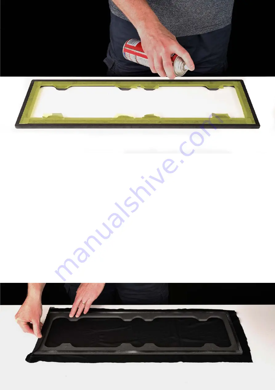
When you’ve finished spraying, turn the can upside down and spray briefly until you notice the 
amount of spray reduces. Usually after about one second, the paint stops but the solvent 
continues. This cleans out the nozzle and avoids blocking next time you want to continue using 
it. Check the nozzle to ensure that it looks clear. If you see any glue there, wipe with a clean 
cloth with mineral turpentine to clean. 
 
Glue is only required on the back surface as shown here – no glue is required to the sides or 
the front.  
 
You can start applying the grille cloth right away but we recommend waiting 2 minutes. Peel off 
the mask with care. A small flat head screwdriver is helpful here to prevent the frame from 
lifting up or flipping over as you remove the masking tape. Hold the frame down with the 
screwdriver in one hand, gently pulling back the tape with the other. Then lay the frame over 
the grille cloth as shown below. 
 
Now press the cloth onto the glue on the back of the frame. Start with one side as shown 
below but avoid the corners, which should be pressed on last. It’s critical that the corners are 
done as the final step to avoid wrinkles bunching up. 
 

Summary of Contents for C6S

Page 1: ...Y Designed and manufactured in Australia by The Loudspeaker Kit www theloudspeakerkit com Email sales theloudspeakerkit com C6S Assembly Instructions...

Page 2: ...ring the work surface avoid using newspaper as newsprint may rub off onto your kit Baking paper is a good choice Easier assembly with mitres LSK kits now employ mitre construction which offers greater...

Page 3: ...the mitres Carefully position sides top and bottom panels Press the panels firmly along each join so that the masking tape on the other side adheres to the MDF Now rotate up each of the four panels as...

Page 4: ...d to all four joins between the rear and adjacent panels This first bead of glue should be applied to the bottom of the mitre Then apply a second bead in the middle of the mitre This bead should be th...

Page 5: ...ue where necessary Fold up the first three panels as shown above Wipe excess glue then firmly press the panels together as you hold them in place with masking tape Initially one strip of tape across t...

Page 6: ...which is yet to be inserted Note in the photo below that the brace is oriented to place the cutout towards the top of the enclosure After the top panel has been glued in place wipe the joins Then hol...

Page 7: ...The entire join should be covered in glue apply more glue where necessary Now press the baffle firmly into place Wipe excess glue and secure with masking tape Secure panels firmly with masking tape a...

Page 8: ...cross the height greater than 220mm Six or more F clamps in total are recommended as shown above Strapping The use of two ratchet straps avoids the necessity of purchasing larger and more expensive F...

Page 9: ...t attachment system that avoids the use of traditional grille clips Flat packs contain neo magnets which have been concealed in the front baffle and grille Sequence tip Final assembly should be done a...

Page 10: ...re shown LOW1 LOW2 it does not matter which woofer is connected to which of these two outputs They are both the same How to identify positive and negative cables All negative cables have a stripe The...

Page 11: ...with the shortest cable pair are near the terminal cut out Installing terminals Find the shortest pair of cables on the crossover board and feed them through the rear terminal cutout Orient the box wi...

Page 12: ...hen the speaker is horizontally oriented as shown on the cover photo The diagram above shows the acoustic lining layout The wire loom from input terminal to crossover runs beneath the larger pieces B...

Page 13: ...needed for the right amount of force This avoids stripping the MDF pre drilled holes or damage to the screw heads If using a screwdriver your left hand can hold the shaft to prevent the head slipping...

Page 14: ...e wire loom for the tweeter and push the connectors onto the driver tabs Caution tweeter terminals are fragile observe instructions on the previous page about how to safely connect the cable without c...

Page 15: ...ch woofer and push the connectors onto the driver tabs Caution Observe instructions on the previous page about how to safely connect the cable without causing damage Insert the provided screws into po...

Page 16: ...llows you to use spray contact adhesive which provides flat and even coverage in addition to a fast application To protect from overspray cover your work surface Adhesive Spray contact adhesive is the...

Page 17: ...here no glue is required to the sides or the front You can start applying the grille cloth right away but we recommend waiting 2 minutes Peel off the mask with care A small flat head screwdriver is h...

Page 18: ...he grille which indicate sufficient tension has been applied Again stop short of the corners Now press the grille cloth to the frame on the third side Then finally press the cloth to the remaining sid...

Page 19: ...ove in the next step Keeping the tension on the cloth transfer the fabric to one hand so that your other hand is free Press out any wrinkles with your finger as shown below If there are some wrinkles...

Page 20: ...g the trench as a guide Tips for a better cut Choose a knife with snap off blades like the one below Stanley knifes are usually too blunt for the job Start with a new blade snap off the previously use...

Page 21: ...g Screws 18mm length 4 x Self tapping Screws 12mm length 2 x 70mm Tuning Ports 4 x Pieces of Acoustic Lining 2 x 180mm W x 260mm L 2 x 290W x 670mm L SPECIFICATIONS Tweeter 1 SB Acoustics SB26ST C0005...

Reviews: