Assembly manual
C6S
Kit
10
Installing the crossover board
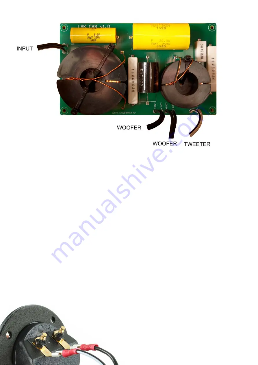
There are three sets of cables:
•
Input terminals:
located near the larger inductor on the end of the board.
•
Tweeter output:
easily identified by the white cable (HI+ HI -)
•
Woofer output:
black cable next to the tweeter outputs (LOW+ LOW-)
The crossover is fixed in place with 4 short button head self tapping screws. It’s best to screw
them in place with a screwdriver by hand. Orient so the input loom is near the terminal cutout.
Note:
Although two sets of woofer outputs are shown (LOW1 & LOW2), it does not matter
which woofer is connected to which of these two outputs. They are both the same.
How to identify positive and negative cables
All negative cables have a stripe. The white tweeter cable has a black stripe. The black woofer
and input cables have a white stripe.
To ensure positive and negative speaker outputs are not reversed, the spade connectors have
different sizes to prevent mistakes. However, extra care is required with the input cable, since
the terminals for this are both of the same size.
Sequence tip:
Normally this step would follow finishing the speaker.
Otherwise sanding will get MDF dust over the crossover.
Note:
The cable with the white strip
goes to the negative terminal


