background image

ALARM AND VIDEO LOSS

When an Alarm occurs, you will see the          icon appear on the channel where motion detection is taking 
place. If you have set the Internal Audible Alarm to ON, then you will also hear a Buzzer.

A Channel that does not have a camera connected will show the   

icon, 

indicating a Video Loss. The red LED light above the channel with a Video Loss 
will blink. If you have set the Internal Audible Alarm to ON, then you will also 
hear a Buzzer when video is disconnected.

The Event List, available from the Menu and shown to the right, lists occurrences 
of Alarms and Video Loss.

RS232 REMOTE PROTOCOL

The RS232 / Alarm input allows you to control the Quad Processor system from your PC. In order to 
achieve this, you will require an RS232 COM Port communication program installed on your PC. There are 
many of these software programs available on the internet, some of which are free.

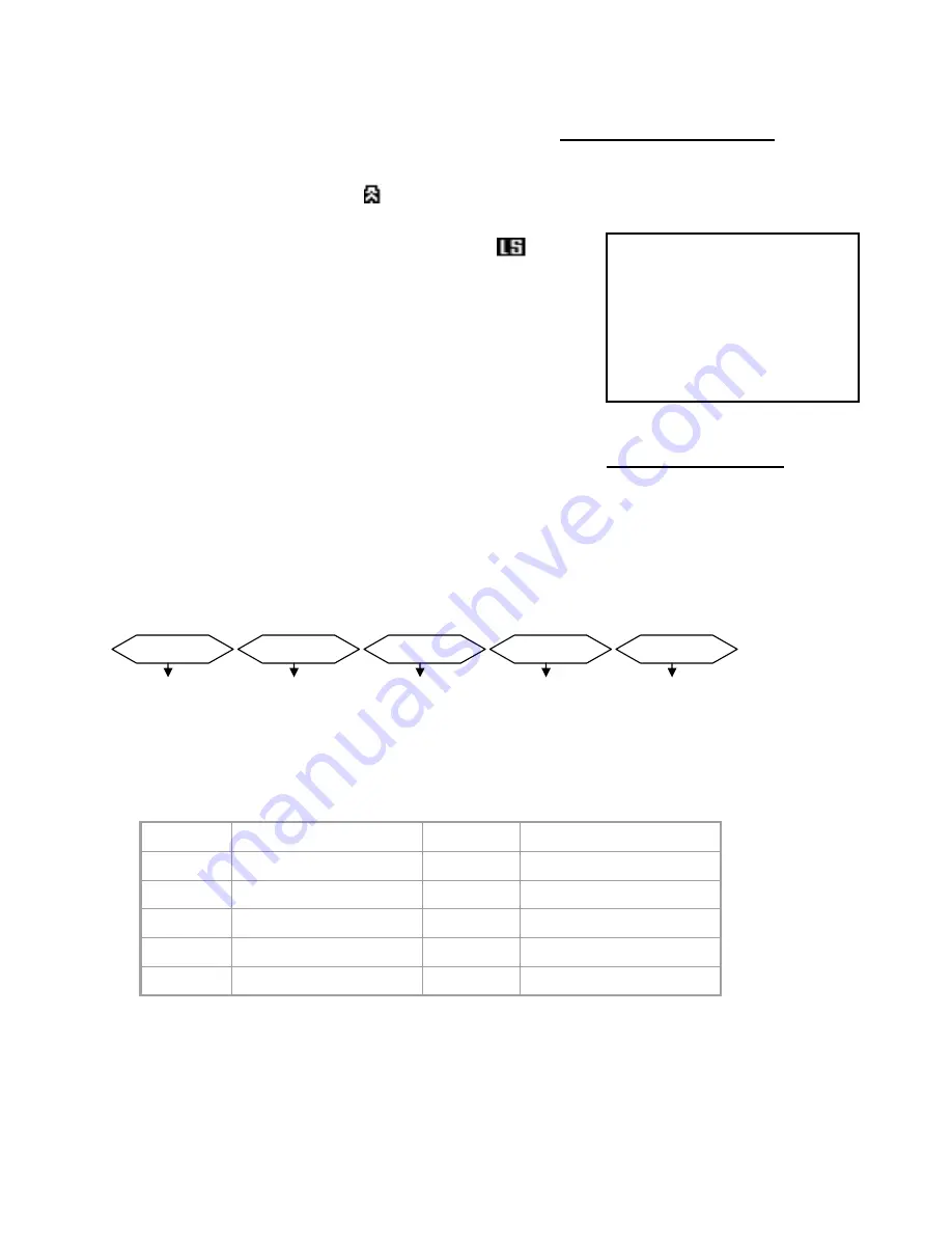
The remote connection on the Quad Processor uses 8 data bits, 1 start bit, and 1 stop bit. 
Below is an example of the data stream with the control codes shown.

The PC keyboard simulates the Quad Processor’s keypad. For example, pressing “V” will make the Quad 
Processor go to VCR mode. Note that the letters are case sensitive. Below is a list of corresponding keys, 
and their codes:

8

For further instructions on connecting the Quad Processor to your PC’s RS232 port, please refer to 
Appendix #4.

ASCII

FUNCTION

ASCII

FUNCTION

A

AUTO

1

CH1

Q

QUAD

2

CH2

M

MENU

3

CH3

V

VCR

4

CH4

F

FREEZE

CH  EVENT YY/MM/DD TIME

------------------------

-----

CH1 VLOSS 01/02/10 

12:20:15

CH2 ALARM 01/02/10 

13:15:10

--- ----- --/--/-- --:--

:--

--- ----- --/--/-- --:--

:--

--- ----- --/--/-- --:--

:--

--- ----- --/--/-- --:--

:--

ACT – OxFF

OxCO

ID

FUNCTION

STOP – Ox7F

Summary of Contents for SGQ4160

Page 1: ...OR Instruction Manual www lorexcctv com Copyright 2005 Strategic Vista International Inc English Version1 0 Please be sure to read carefully and follow all the safety information Keep the manual in a...

Page 2: ...footage and enable alarm recording You can also connect PIR motion sensors to the Quad Processor in order to have Motion Detection capability To learn more about this system or to find out more about...

Page 3: ...yourself Refer all servicing to qualified service personnel This unit should be operated only from the type of power source indicated on the manufacturer s label This installation should conform to al...

Page 4: ...LARM AND VIDEO LOSS 8 RS232 REMOTE PROTOCOL 9 TROUBLESHOOTING 10 TECHNICAL SPECIFICATIONS 11 APPENDIX 1 TYPICAL CONFIGURATION 12 APPENDIX 2 CONNECTION TO A PIR MOTION SENSOR 13 APPENDIX 3 CONNECTION T...

Page 5: ...ns in Menu mode 3 Exits the Menu screen Pressing this button goes to Full Screen display of Camera 1 It also serves as the Up arrow key in Menu mode Pressing this button goes to Full Screen display of...

Page 6: ...s by pressing their respective buttons To exit Freeze mode press the VCR PLAY FREEZE ENTER button a second time 3 In Menu mode pressing this button selects a menu option to be edited 6 7 8 LED INDICAT...

Page 7: ...99 seconds Use buttons to increase decrease duration times Baud Rate Set the speed of the remote computer s Baud Rate which is the rate of data transmission Available Baud Rates are 1200 2400 3600 480...

Page 8: ...le Alarms Alternatively connect this terminal to a PC refer to page 13 and control system functions via a PC 1 2 3 4 5 6 1 VIDEO INPUT 2 3 500 mA DC 12V OUT QUAD VCR 4 IN OUT MONITOR ALARM 1 2 5 3 4 6...

Page 9: ...In order to achieve this you will require an RS232 COM Port communication program installed on your PC There are many of these software programs available on the internet some of which are free The re...

Page 10: ...e Quad Processor is correct Make sure that the camera is receiving power Unable to view cameras REMEDY PROBLEM TROUBLESHOOTING 9 TECHNICAL SPECIFICATIONS Because our products are subject to continuous...

Page 11: ...in AUX mode sometimes referred to as TV Video THE COLOR QUAD HAS BNC JACKS TO CONNECT TO OTHER VIDEO SOURCES BNC COUPLERS AND VIDEO CABLES ARE NOT INCLUDED 10 APPENDIX 1 TYPICAL CONFIGURATION 1 VIDEO...

Page 12: ...res from the PIR Motion Sensors must be soldered to the terminal of the 9 Pin Alarm Connector Each PIR Sensor connects via 2 wires 1 to a specific Channel and the other to the Ground input For descrip...

Page 13: ...ust be soldered to the appropriate terminal of the 9 Pin Alarm Connector In addition to connecting up to 4 PIR Motion Sensors connect the 9 Pin Alarm Connector to a security recorder such as the Lorex...

Page 14: ...APPENDIX 4 PIN CONFIGURATIONS FOR CONNECTION TO A COMPUTER 13 25 PIN COM PORT 9 PIN COM PORT...

Page 15: ...all on the web www lorexcctv com Product Information User Manuals Quick Start Guides Specification Sheets Software Upgrades Firmware Upgrades V I S I T Strategic Vista International Inc www lorexcctv...

Reviews: