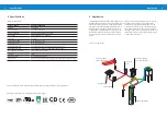
6 Application
Application 7
4.1 IMPORTANT - Using PP2000S with
PS2-600
l
WARNING
– Before changing power
sources, the PowerPack and controller
must be switched off and the AC and DC
power sources must be disconnected.
WARNING
– The following feature
should only be operated by qualified
personnel.
The PP2000S is delivered with default settings for
PS2-1800 systems. If you are using the PowerPack
with a PS2-600 system then please adjust the voltage
as described below and in table 2.
Position 1 is for PS2-600 and Position 4 is for PS2-
1800.
Table 2: Optional voltage selection
Voltage
selection
DC
voltage
value
Description
Pos 1.
135 V
Mandatory position
for all the PS2-600
pump systems
Pos 4.
160 V
Default position
for all the PS2-1800
pump systems
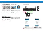
Figure 3:
PP2000S remote on/off wiring
Figure 4:
PumpScanner feature settings and 24/7 operation configuration
Well probe
Sun Sensor
Pump
PowerPack
PP2000S
PS2-1800 controller
PS2-600 controller
PV generator
Grid power
DC
POWER
OUT (max.
200V DC)
SOLAR
POWER IN
(max. 200V
DC)
Remot
e
On/O
ff
1 2 GND
+
+
–
–
N
L
AC
POWER IN
(240V/50-60Hz)
v210615
SOLAR
IN
Well
probe
Remote
switch
Water
meter
Analog 1
4-20mA
Analog 2
4-20mA
Out
Water
sensor
Sun
Sensor
Pump
+
–
1
2
3
4
5
6
7
8
9
10 11 12 13 14 15 16 17
L1 L2 L3
com
com
com +24V
+24V
+24V
com
+
–
a
CAUTION
– AC power must be available
at all times to prevent the pump from
running with insufficient power (e.g.
idling).
a
CAUTION
– A Sun Sensor must
be installed and configured for 24/7
operation.
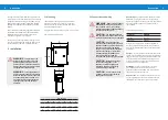
Figure 2: Voltage switch selector
The default selector position should only be changed
when using this PowerPack with a PS2-600 system.
COMPASS can be used to check the expected
performance of your system based on the selected
voltage setting.
4.2
Remote on/off function
This PowerPack includes a normally open (NO)
terminal for remote control. Closing the contact
between the remote on/off terminals will switch off
the DC output of the PowerPack.
The PP2000S allows 24/7 operation of the LORENTZ
PS2-1800 / PS2-600 pump systems by connecting the
output switch of the controller to the remote on/off
terminals in the PowerPack. This is shown in figure 3.


