- 67 -
service manual
mod. 051135
7
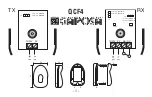
N
P
R
Q
H
L
M
H1
H2
4 - Tighten the screws (M) temporarily in
alternating pattern.
5 - Tighten the screws (L) in a crisscross
pattern to a final torque of 50Nm.
6 - Tighten the screws (M) in an alternating
pattern to a final torque of 10Nm.
7.5.4 Measuring crankshaft axial clearance
To measure the axial clearance of the
crankshaft, it is necessary to assemble the
shaft complete with crankcase.
See “Assembling the crankcase” for the correct
procedure.
1 - Using a dial indicator, measure the axial
shift of the crankshaft.
Axial shift must be between 0.130 and
0.313mm. If axial shift is above these
values, it is necessary to insert uprated
shoulder half-rings and once again
disassemble the crankcase (see
“Dimensional check and overhaul of
crankshaft”).
7.5.5 Assembling the crankshaft flange
(flywheel side)
1 - Clean the flange and the sealing ring seat
(N).
2 - Using the special pad, insert a new sealing
ring (N) into the flange (Q).
Important
Given the particular function played by this
sealing ring, it is important to use only
original spares.
3 - Check that the contact surfaces are
perfectly clean and intact.
engine block
INSTALLATION OF ASSEMBLIES
Summary of Contents for LDW 502
Page 1: ...SERVICE MANUAL code 1 5302 727 ...
Page 8: ... 8 service manual mod 051135 Notes GENERAL REMARKS AND SAFETY ...
Page 22: ... 22 service manual mod 051135 2 Notes TECHNICAL INFORMATION ...
Page 24: ... 24 service manual mod 051135 3 MALFUNCTIONS ...
Page 28: ... 28 service manual mod 051135 4 STORING THE ENGINE ...
Page 62: ... 62 service manual mod 051135 6 OVERHAULS AND TUNING ...
Page 82: ... 82 service manual mod 051135 7 Notes INSTALLATION OF ASSEMBLIES ...
Page 94: ... 94 service manual mod 051135 8 Notes REPLACING PARTS ...