


Installation Guide
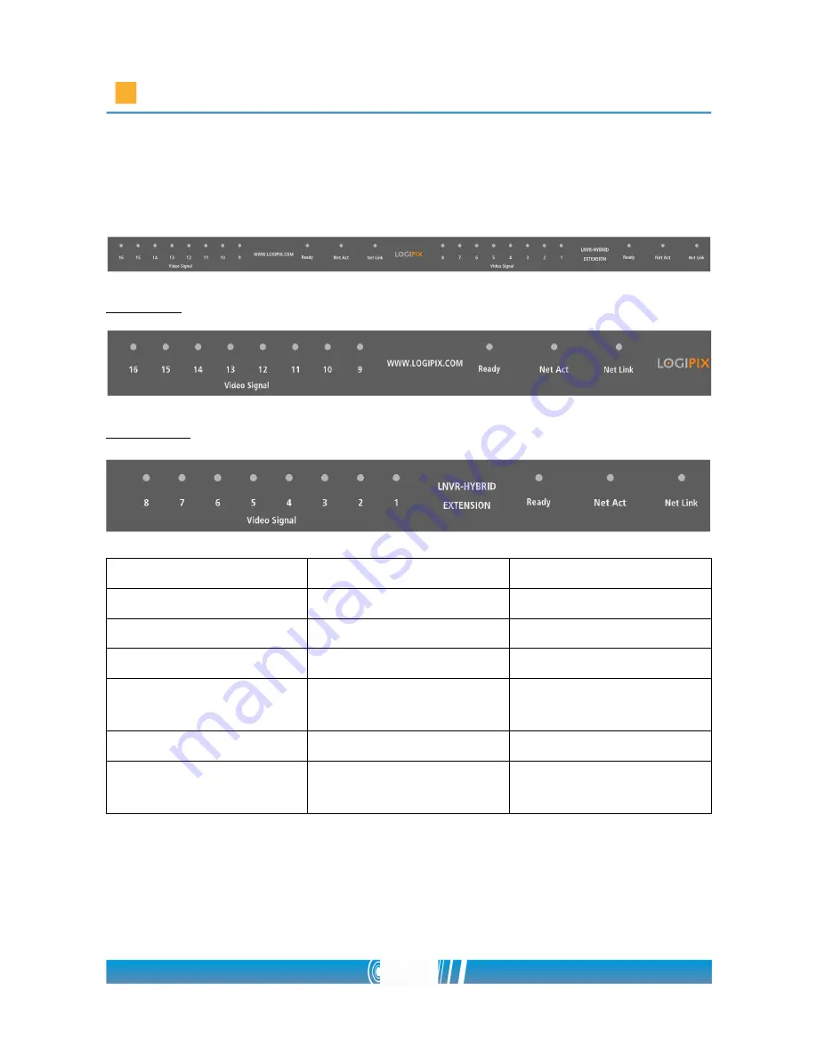
Checking LED information
The left side
The right side
LED
Status
Description
Ready LED
Blinking red
Normal operation
Net Link LED
Lights up in orange
Network link present
Net Act LED
Blinking green
Network communication
Camera LEDs (Video
Signal)
Lights up green
Normal operation
Dark
Input not configured
Blinking green
Input configured, but
bad / no video signal
27/80


