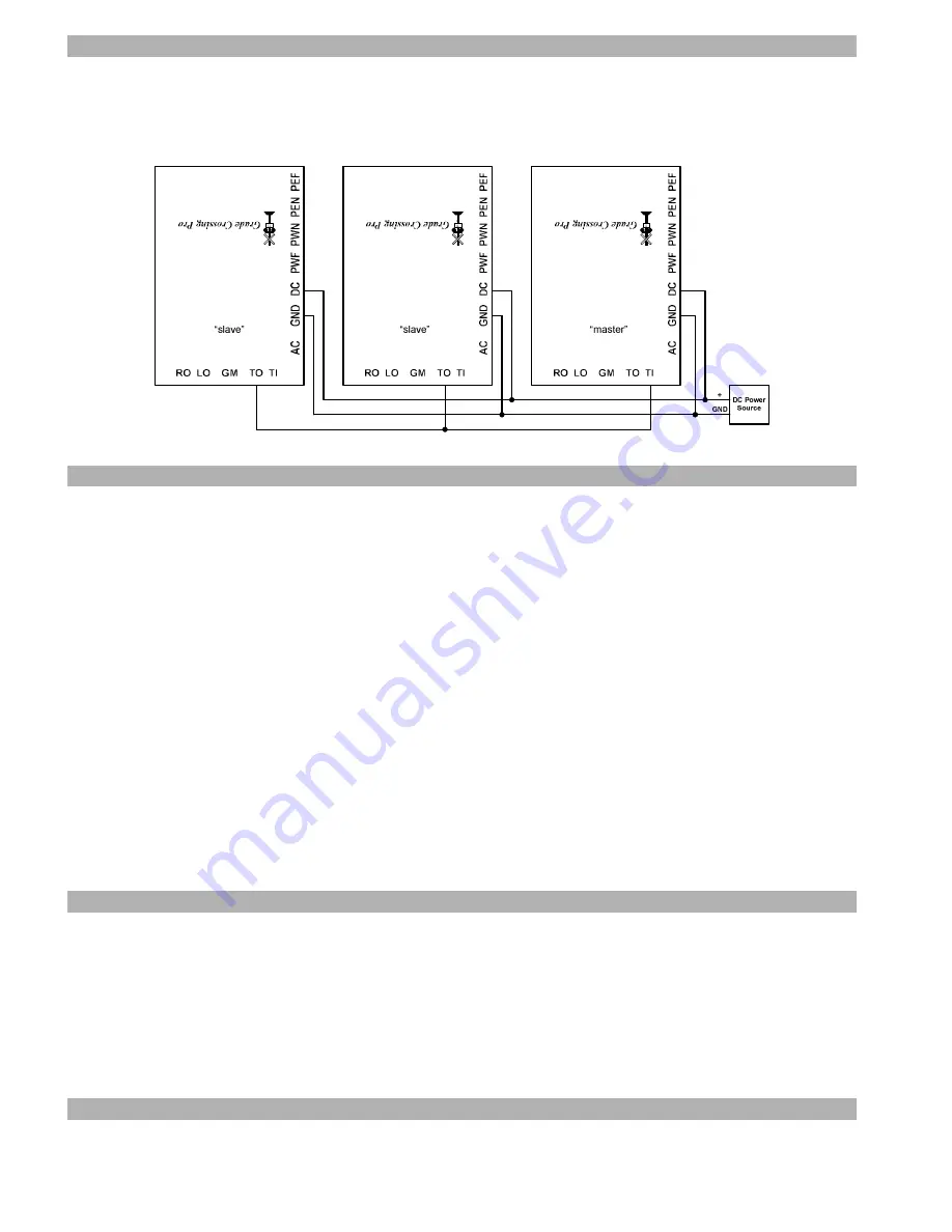
Cascading Multiple GCPs for multi-track grade crossings
The “TI” and “TO” terminals on the GCP are used for cascading multiple GCPs when you have a multi-track crossing. You
must use one GCP per track and you MUST use the SAME DC power source (as shown in Figure 9 below) for all cascaded
GCPs. You will denote ONE GCP as the “master” and the others as “slaves”. The
master provides detection for one track
and receives “triggers” from the slaves and provides the signal and motor outputs
; the slaves only provide detection via
their own sensors and
do not utilize their signal or motor outputs
. Figure 9 illustrates the wiring for a 3 track set up.
R
AI
L
R
O
AD
C
R
O
S
SI
N
G
R
AI
L
R
O
AD
C
R
O
S
SI
N
G
R
AI
L
R
O
AD
C
R
O
S
SI
N
G
Figure 9 – Cascading Multiple GCPs
Troubleshooting
If your signals do not flash when a particular sensor is activated then you can perform the following tests. First, perform the
sensor setup routine previously described. If one or more of the sensors does not function properly then you know it is faulty. If
the sensors are OK then you might have a problem with the GCP, the signals, or the wiring between them.
If the red LED on the GCP board stays lit when the GCP is in SETUP mode then there is a problem with: sensor sensitivity,
sensor wiring, or one of the chips on the GCP. First, double-check your sensor wiring. A missing sensor connection (missing
wire or open circuit) will be interpreted by the GCP as a cleared sensor. A shorted sensor (i.e. blue and black wires touching)
will be interpreted by the GCP as an activated sensor. Next, put the GCP in SETUP mode (see page 1) and turn all four sensor
sensitivity pots completely clockwise (right). If the red LED goes out then simply complete the sensor setup process
continuing with Step 4 on page 4. If the red LED is still lit then the problem is either a bad sensor or a faulty chip on the
GCP.
You can determine if the GCP sensing chip is working correctly by TEMPORARILY disconnecting all blue sensor wires
from the GCP. If the red LED on the GCP is lit then its sensing chip is faulty (read on below for details on replacing it). If, on
the other hand, the red LED on the GCP is now dark then connect each sensor input (PWF, PWN, PEN, PEF) to GND, ONE
sensor input at a time. An activated sensor appears to the GCP like a connection to GND so you are, in effect, mimicking an
activated sensor with this test. If the red LED does NOT come on each time you make that temporary connection (make sure
you try all four sensor inputs!) then you have a faulty chip.
The chip that “processes” the sensor inputs is located closest to the sensor sensitivity pots. This chip is labeled “LM339”.
Replacements are available from us or you might find one from stores such as Radio Shack. To replace the chip you will
need to gently pry it out of its socket using a flat blade screwdriver. Take great care when inserting the replacement chip so
that you don’t bend any of its pins underneath it. Make sure the text on the chip has the same orientation as the name “Grade
Crossing Pro” on the circuit board. Still having problems?! Please contact us for further assistance!
Warranty
This product is warranted to be free from defects in materials or workmanship for a period of one year from the date of purchase.
Logic Rail Technologies
reserves the right to repair or replace a defective product. The product must be returned to
Logic Rail
Technologies
in satisfactory condition. This warranty covers all defects incurred during normal use of this product. This
warranty is void under the following conditions:
1) If damage to the product results from mishandling or abuse.
2) If the product has been altered in any way (e.g. soldering).
3) If the current or voltage limitations of the product have been exceeded.
Requests for warranty service must include a dated proof of purchase, a written description of the problem, and return shipping
and handling ($7.50 inside U.S./$20.00 outside U.S. - U.S. funds only). Except as written above, no other warranty or
guarantee, either expressed or implied by any other person, firm or corporation, applies to this product.
Technical Support
We hope the preceding instructions are sufficient for answering any questions you might have about the installation of this
product. If you require technical support please do not hesitate to contact us by phone, mail and email; our contact information
can be found on page 1.


