


L o g a n G r a p h i c P r o d u c t s I n c . , 1 1 0 0 B r o w n S t r e e t , Wa u c o n d a , I L 6 0 0 8 4 To l l F r e e 1 8 0 0 3 3 1 6 2 3 2 w w w. l o g a n g r a p h i c . c o m
8
FRAMER'S
EDGE
C O U T E A U X À PA S S E - PA R T O U T
MODÈLES 650, 655 ET 660
C O R TA D O R D E L Á M I N A P E R I M É T R I C A
MODELOS 650, 655 Y 660
PA S S E PA R T O U T S C H N E I D E R
MODELLE
650, 655 & 660
TA G L I E R I N E P E R PA S S E PA R T O U T
MODELLI 650, 655 E 660
FRAMER'S
EDGE
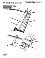
Fig 1
Fig 2
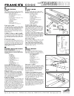
Fig 3
Fig 4
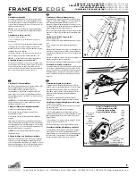
Fig 5
Commencez à partir du
point vert.
Comience en el punto
verde.
Beginnen Sie am
grünen Punkt.
Partire dal punto verde.
Arrêtez-vous au point
rouge
Pare en el punto rojo.
Stoppen Sie am roten
Punkt.
Fermarsi sul punto
rosso.
Faites pivoter le support
de lame.
Rote el sujetador de la
cuchilla.
Drehen Sie das
Klingenmagazin
Ruotare il portalama.
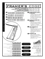
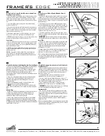
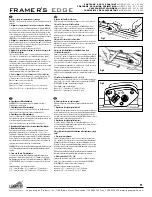
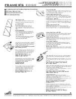
B. Découpe d’une fenêtre avec biseau en utilisant les lignes de repère
1. Mettez toujours une feuille doublure de protection quand vous découpez en biseau.
2. Pour relâcher le rail parallèle, desserrez les boutons noirs de deux tours. Faites
glisser le rail parallèle dans ses conduits, jusqu'à la largeur de bord souhaitée. Fig. 1
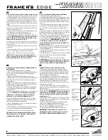
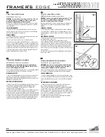
3. Levez la guide rail avec poignée et placez une feuille doublure sur le plateau d
travail. Puis placez votre passe-partout aux dimensions prédéfinies avec le côté coloré
positionné vers le bas contre le bras d’équerrage, la partie gauche calée contre le rail
parallèle.
4. Abaissez le guide rail avec la poignée. Avec un crayon, tracez une ligne au dos du
passe-partout en vous servant du rail parallèle comme règle. Recommencez pour les
trois autres côtés du passe-partout. Fig. 2
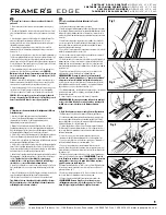
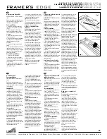
5. Faites glisser la tête de découpe de façon à ce que le bord du métal près du point
vert sur la plaque repère soit exactement sur la ligne tracée. Fig. 3
point vert de la plaque repère soit exactement sur la ligne tracée. Fig. 3
6. Faites pivoter le support de lame à biseau vers le bas afin d’insérer la lame dans le
passe-partout.
CONSEIL : Maintenez la tête de découpe fermement pour
qu’elle ne dévie pas lors de la première entame de la lame, ce qui
aurait pour effet de produire une surcoupe.
Fig. 4.
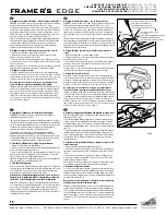
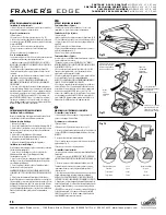
En exerçant une pression vers le bas, tirez la tête de découpe vers vous jusqu’à ce que
le bord du métal près du point rouge de la plaque repère soit exactement sur la ligne
inférieure tracée. Fig. 5
7. Faites pivoter le support de lame à biseau en position neutre et levez la poignée en
position verticale.
8. Tournez le passe-partout de 1/4 de tour vers la droite et assurez-vous qu’il est calé
en bas contre le bras d’équerrage et sur la gauche contre le rail parallèle.
9. Répétez les étapes 5 à 8 jusqu’à ce que les quatre côtés soient découpés.
CONSEIL : N’exercez pas de pression sur la poignée pendant la
découpe, cela aurait pour effet d'incurver le rail de guidage vers le
haut et empêcherait la lame de couper le passe-partout.
B. Corte de una Abertura Biselada Utilizando Líneas Marcadas
1. Utilice siempre una hoja de respaldo cuando corte biseles.
2. Para liberar la guía de la lámina perimétrica afloje las perillas negras dos vueltas.
Deslice la guía de la lámina perimétrica en las ranuras anguladas hasta que el borde
delantero de la guía de lámina perimétrica esté alineado con el incremento de la
escala de la guía de la lámina perimétrica a la anchura de la franja que usted desea
cortar. Fig. 1
3. Eleve la barra de la manija y coloque una hoja de respaldo sobre el tablero de
corte. Luego ponga su lado pre-medido del tablero de lámina perimétrica de color
abajo contra el brazo de escuadra y a la izquierda contra la guía de la lámina
perimétrica.
4. Baje la barra de la manija. Con un lápiz dibuje una línea en el dorso del tablero
de la lámina perimétrica utilizando el lado izquierdo de la barra de corte como guía.
Haga esto para los tres lados restantes de la lámina perimétrica. Fig. 2
5. Deslice la cabeza de corte en posición de modo que el borde del metal cerca del
punto verde en la placa indicadora está directamente sobre la línea marcada. Fig. 3
6. Rote el sujetador de la cuchilla de bisel totalmente para que asiente la cuchilla
dentro de la lámina perimétrica.
RECOMENDACIÓN: Retenga la cabeza de
corte firmemente lo suficiente como para no permitirle que se
"arrastre hacia adelante" al empezar a insertar la cuchilla lo cual
producirá un sobrecorte.
Fig. 4
Manteniendo la presión hacia abajo, tire de la cabeza de corte hacia usted hasta que
el borde del metal cerca del punto rojo en la placa indicadora esté directamente
sobre la línea marcada abajo. Fig. 5
7. Rote el sujetador de la cuchilla de bisel hasta la posición neutral y eleve la barra
de la manija a una posición vertical.
8. Gire la lámina perimétrica _ de vuelta hacia la derecha y asegúrese que la lámina
perimétrica esté contra el brazo de escuadra y contra la guía de la lámina
perimétrica de la izquierda.
9. Continúe los pasos 5 a 8 hasta que estén cortados los cuatro lados.
RECOMENDACIÓN: No empuje hacia abajo la barra de la manija al
cortar, esto doblará la barra de corte hacia arriba y evitará que la
cuchilla corte a través del tablero de la lámina perimétrica.
B. Schneiden eines Fensterausschnitts mit Schrägkante anhand von
Markierungslinien
1. Verwenden Sie beim Schrägschnitt immer einen Unterlagekarton.
2. Lockern Sie die Passepartoutführung mit zwei Umdrehungen der beiden schwarzen
Knöpfe. Verschieben Sie die Passepartoutführung auf die Skalamarkierung der
gewünschten Breite. Abb. 1
3. Klappen Sie die Schneidschiene mit dem Griff auf und schieben Sie einen
Unterlagekarton darunter. Legen Sie einen Passepartoutkarton der gewünschten Größe
mit der farbigen Seite nach unten fest an den Anschlagarm und links gegen die
Passepartoutführung.
4. Klappen Sie den Griff nach unten. Ziehen Sie auf der Rückseite des Kartons eine
Bleistiftlinie entlang des linken Randes der Schneidschiene. Wiederholen Sie dies für
die drei weiteren Seiten des Passepartoutkartons. Abb. 2
5. Verschieben Sie den Schneidkopf so, dass die Metallkante des Anzeigeplättchens,
die sich oberhalb des grünen Punktes befindet, genau mit der oberen Bleistiftlinie
übereinstimmt. Abb. 3
6. Drücken Sie das Klingenmagazin vollständig nach unten, so dass die Klinge in den
Karton einsticht.
TIPP: Halten Sie den Schneidkopf fest genug um zu
verhindern, dass er sich nach vorn verschiebt, wenn die Klinge
einsticht, da es sonst zu Überschnitten kommen kann.
Abb. 4.
Ziehen Sie den Schneidkopf unter Ausübung von Druck soweit auf sich zu, bis die
Metallkante des Anzeigeplättchens, die sich oberhalb des roten Punktes befindet,
genau mit der unteren Bleistiftlinie übereinstimmt. Abb. 5
7. Drehen Sie das Klingenmagazin nach oben in seine neutrale Position. Klappen Sie
die Schneidschiene mit dem Griff nach oben.
8. Drehen Sie den Karton um eine Viertel Drehung nach rechts und schieben Sie ihn
erneut fest and den Anschlagarm und links an die Passepartoutführung.
9. Wiederholen Sie die Schritte 5 bis 8 bis alle vier Seiten geschnitten sind.
Tipp: Drücken Sie beim Schneiden nicht auf den Griff des Gerätes.
Dies kann bewirken, dass der Schneidkopf sich anhebt und nicht
vollständig durch den Karton schneidet.
B. Taglio di un’apertura a smusso usando linee tracciate
1. Utilizzare sempre un foglio di rinforzo quando si effettuano tagli a smusso.
2. Per rilasciare la guida del passepartout, allentare le manopole nere di due giri.
Far scorrere la guida del passepartout nelle scanalature angolate finché il bordo
anteriore della guida non si trovi lungo l’incremento del righello della guida della
larghezza del margine che si desidera tagliare. Fig. 1
3. Sollevare l'impugnatura e collocare un foglio di rinforzo sul pannello di taglio.
Posizionare quindi il cartoncino predimensionato con il lato colorato rivolto verso il
basso contro il braccio di squadratura e a sinistra contro la guida del passepartout.
4. Abbassare l’impugnatura. Con una matita, tracciare una linea sul retro del
cartoncino utilizzando il lato sinistro della barra di taglio come guida. Ripetere per i
tre lati rimanenti del passepartout. Fig. 2
5. Far scorrere la testa di taglio in posizione così che il bordo del metallo in
prossimità del punto verde sulla piastra indicatrice si trovi direttamente al di sopra
della linea tracciata. Fig. 3
6. Ruotare completamente verso il basso il portalama per tagli a smusso per inserire
la lama nel passepartout.
SUGGERIMENTO: Tenere la testa di taglio con
sufficiente fermezza per impedirle di spostarsi in avanti quando si
inserisce per la prima volta la lama, in quanto potrebbe produrre
un taglio impreciso.
Fig. 4
Esercitando pressione, tirare la testa di taglio verso di sé finché il bordo del metallo
in prossimità del punto rosso sulla piastra indicatrice non si trovi direttamente al di
sopra della linea tracciata inferiore. Fig. 5
7. Ruotare verso l’alto il portalama per tagli a smusso portandolo in posizione
neutrale e sollevare l'impugnatura portandola in posizione verticale.
8. Ruotare verso destra il passepartout di 1/4 di giro e accertarsi che si trovi in
basso contro il braccio di squadratura e a sinistra contro la guida.
9. Eseguire le procedure dalla 5 alla 8 fino a tagliare tutti e quattro i lati.
SUGGERIMENTO: Durante il taglio, non esercitare pressione
sull’impugnatura in quanto ciò potrebbe piegare verso l’alto la
barra di taglio e impedire alla lama di tagliare il cartoncino.


