


Sawyer Manufacturing Company
7799 S. Regency Dr., Tulsa, OK 74131 USA
F
918.834.0318
We appreciate your business!
Congratulations on your new SAWYER product. We are proud to
have you as our customer and will strive to provide you with the best
service and reliability in the industry. This product is backed by our
extensive warranty and world-wide service network. To locate your
nearest distributor or service agency, please contact us at the phone
number and address listed on the bottom of each page.
You are in good company!
Sawyer Manufacturing Company is the world leader in the design
and manufacture of pipeline and welding equipment and has been
since 1948. Sawyer equipment has become a standard in the industry
and continues to set the benchmark for quality and durability.
This user operation manual has been made to instruct you for the best
use and operation of your Sawyer product. Your satisfaction with our
products is our main goal. Please read this entire manual carefully,
noting all tips, notes and warnings. Safety always comes first.
About Us
Warranty
All products manufactured by or for Sawyer Manufacturing Company are
guaranteed against defects due to faulty workmanship or materials for twelve
months from the date of purchase.
This guarantee is limited to the repair or replacement of any parts found to be
defective, and no other liability–expressed, implied, or contingent–is assumed.
Record the following information for warranty purposes:
Where purchased:________________________________________________
Purchase date:___________________________________________________
Equipment Serial #:_______________________________________________
P
918.834.2550
sawyermfg.com
V1
A
W
B
C
G
D
U
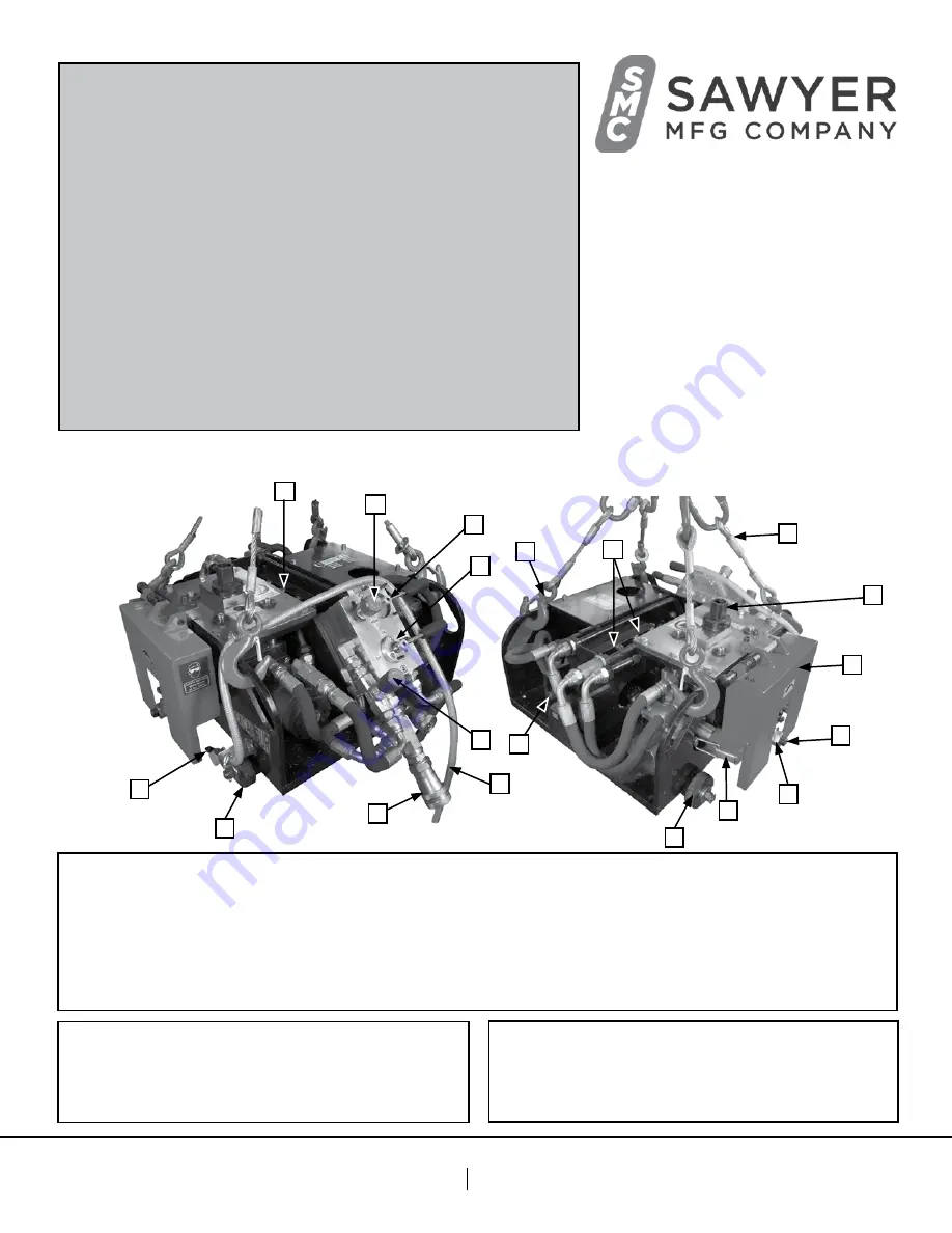
Excalibur Manual
Cold Cutting Model 210
Parts Diagram - 210H
210H - Oil (Hydraulic Driven)
210E - Electric (Electric Driven)
210P - Air (Pneumatic Driven)
L
K
E
F
I
J
O
N
Q
T
Q
V
A.
Blade Speed Control
B.
Start/Stop Control
C.
Machine Directional Control
D.
Machine Speed Control
E.
Feed Screw
F.
Lifting Cables
G.
Lifting Spring Clips
H.
Blade Lowering/Raising Handle
(not shown)
I.
Blade Safety Cover
J.
Cutter Spindle
K.
Blade Safety Device
L.
Cutter Lock Nut & Cutter Collar Support
M.
Milling Cutter
(not shown)
N.
Lubricator Nozzle
O.
Mist Lubrication System Hose
P.
Coolant Container
(not shown)
Q.
Guide Wheels
R.
Guide Wheel Tracks
(not shown)
S.
Socket Head Cap Screws
(not shown)
T.
Hydraulic Hose Connector
U.
Drive Chain
(not shown)
V.
Drive Chain Sprockets
W.
Chain Tensioning Screw
X.
Single Chain Pin
(not shown)


