background image

Doc. Ref.No: Q875-0143/ENG


Issue 2 

Met 30+ Operating Manual


12/01/10 


10. TROUBLESHOOTING 

GUIDE 

The aim of this section is to list common problems and possible solutions. The fault 
finding section of the Installation Manual should also be consulted. 


10.1 False Triggering/Poor Sensitivity 

This is the most common problem with metal detectors. There are many possible 
reasons for it, so the first thing to do is to narrow down the source of the problem. To 
do this, select the "TEST SETUP" preset and pass the test sample provided through 
the metal detector. Now read the relevant paragraph below: 

10.2 Fails to detect test sample 

The detector is now less sensitive than when it left Lock Inspection. An engineer 
should check that the power supply cables are wired correctly. If everything appears 
to be OK call Lock. 

10.3 Detects sample but false triggers 

There are many possible reasons for this, below is a list of possible causes: 
 
Components guiding/transferring products through the metal detector should be 
clean and contain no metal. Sometimes metal becomes embedded in the 
guiding/transferring components causing the head to trigger at regular intervals. 
Under no circumstances should metal fasteners be used in guiding/transferring 
components. 
 
Moving metal in the metal-free-zone - there must be no metal in the metal-free zone. 
Consult the Installation manual. 
 
Earth loops - all metal items must be securely bonded to each other or insulated. 
Intermittent metal-to-metal contacts can often cause problems. 
 
Electrical interference - all high-current cables should be routed well away from the 
detector and its cabling. 

File Name: Q875-0143 ENG Iss2 Met30+ Operating.doc 

Page 56 of 58


Summary of Contents for MET 30+

Page 1: ...INSPECTION SYSTEMS M ME ET T 3 30 0 Metal Detectors Operating Manual...

Page 2: ...Manual Q875 0143 ENG Issue 2 Models Covered Met30 VFD Touch Screen Software Version 4 xx Supplied By 2010 LOCK Inspection Systems Ltd Lock House Neville Street Oldham Lancs OL9 6LF Tel 0161 624 0333 F...

Page 3: ...connection with the use of this document Lock Inspection Systems Limited reserves the right to change the contents of this document at any time without prior notice having been given Amendments Lock...

Page 4: ...7 3 3 Orientation Effects 8 3 4 Sensitivity Gradient 9 3 5 Product Effect 9 3 6 Scope Of This Manual 9 4 SETTING UP THE MACHINE 11 4 1 Detector Display and Keypad 11 4 2 Initial Test 12 4 3 Product S...

Page 5: ...rt 35 8 PRINTER 36 8 1 Print Modes 37 8 2 Reports 40 8 3 Engineering Setup 43 8 4 Printer Cable Diagrams 44 9 TOUCH SCREEN DISPLAYS 45 9 1 ADC Screen 46 9 2 Reports Display 51 9 3 Met30 1f System Menu...

Page 6: ...p 57 11 4 False Triggering 57 11 5 Metal Free Zone 57 11 6 Noise 57 11 7 Noise Test 57 11 8 Product Effect 57 11 9 Sensitivity 58 11 10 Systemchek 58 11 11 Test Sample 58 11 12 Trigger 58 11 13 VFD Va...

Page 7: ...t Work etc Act The Purchaser shall comply with the instructions and information of this manual and it is strongly advised that all personnel associated with this equipment be made familiar with the in...

Page 8: ...cification will distort the electromagnetic field and be detected no matter how deeply embedded in the product On detection a reject relay is activated this relay is used to switch the automatic rejec...

Page 9: ...velope See fig 1a and 1b You can alter the sensitivity of the detector by increasing or decreasing the dimensions of the envelope known as the width and height Increasing the envelope size decreases t...

Page 10: ...be noticed The wire will be detected more easily with its long axis presented one way into the aperture than it will be when presented in another See figure 1c Figure 1c shows that when a piece of no...

Page 11: ...effect signals are ignored during production thus preventing false detection If a product has any effect then the resulting detection envelope will be bigger this bigger envelope will therefore resul...

Page 12: ...ipped with a Touch Screen display there are a number variations in operation and additional features which take advantage of a larger display Touch Screen users should consult the Touch Screen Display...

Page 13: ...ers and after power on or reset the top line shows the current product name and the bottom line shows a bargraph The bargraph can be used to see how good a product setup is the circles show the size o...

Page 14: ...the metal detector to learn the characteristics of a particular product In order to do this some product samples will be required The description of how to use the software is kept deliberately brief...

Page 15: ...tup If the detector does trigger on the product read the notes below Notes on automatic setup The detector will usually be able to set itself up automatically however the following points should be bo...

Page 16: ...to it i e whether it is variable speed and whether there is a product gating photocell or not To tell the detector about the system connected to it enable the relevant timer inputs and adjust their po...

Page 17: ...t relay remains active for can be changed by adjusting the reject time If there are many triggers the reject relay will be activated after the correct delay for each trigger For an immediate reject se...

Page 18: ...R is shown in the top right hand corner of the display when a reject is triggered Once the reject and photocell delay times have been set up the delay and alarm times need setting If these times are...

Page 19: ...signal P Phase of signal Met30 Standard Met30 Pharmaceutical Prod count 31473 S 92 P 45 0 Rej count 12 Rej count 12 The next screen to be displayed shows detection parameters Met30 1f Met30 3f W 100...

Page 20: ...text and would typically be used to show the serial number of the head its frequency etc The next screen shows Machine type For lock service engineers only Pharmaceutical Intermediate VFD The top line...

Page 21: ...configured The test tacho function allows you to view the tacho sensor pulses on a variable speed conveyor system The conveyor must be switched ON for this display to show the correct information Sec...

Page 22: ...l sample If the detector fails to detect metal in this time it displays the message TEST FAILED and waits for the SELECT key to be pressed and returns to the TEST menu If metal has been detected then...

Page 23: ...he letters have the following meanings T Do sample test P Select product R Print report C Clear counts S Setup product r Adjust reject timers E Edit product D Delete product o Operator s code e Engine...

Page 24: ...d displayed to finish name entry Product names may be up to 20 characters in length 5 4 5 2 Adjust Old Product If Adjust old product is selected scroll through the list of products and select one in t...

Page 25: ...the delay time and photocell delay time are measured in pulses instead of hundredths of a second While in this option the letter R is displayed in the top right corner of the screen when a reject occ...

Page 26: ...ph to see how close to false triggering the detector is 5 4 7 3 Height Adjustment H This option allows adjustment of the height of the detection envelope see the diagram of the Product Detection Envel...

Page 27: ...mation will be asked for If NO is selected then no action is taken and the option is exited If the current product is deleted the detector will switch to running the TEST SETUP 5 4 9 Operator s Code o...

Page 28: ...cate that the sample test is overdue The display is reset by the SELECT key This optional feature is detailed in the Sample Test section of this manual 5 5 2 Configure System c This option also has a...

Page 29: ...Aux allows the fifth timer input CN13 on the power supply to be used in a variety of applications for example as an air failure detector or bin full sensor To use this facility proceed as follows firs...

Page 30: ...4 Set System Clock T The display shows the current date DD MM YY and time HH MM SS Enter date and time 25 01 07 14 24 18 Initially the date will be high lighted Use the keys to change the date Press S...

Page 31: ...t by the SELECT key The three printer options are also cycled with the or keys and set by the SELECT key The three options are Printing disabled i e No printer output Print on demand i e printer outpu...

Page 32: ...ct Height P Product Phase G Adjust gain x Exit Configure System Inputs Syschek Aux Exit Engineering Setup Menu S Sample test reminder c Configure system v Vibration setup T Set system clock C Communic...

Page 33: ...uct Phase G Adjust gain F Switch Freq x Exit Configure System Inputs Syschek Aux Exit Engineering Setup Menu S Sample test reminder c Configure system v Vibration setup T Set system clock C Communicat...

Page 34: ...inder facility is shown in the Sample Test Flowchart Section This shows the messages given on the detector s display the lights on the tower if fitted the state of the detector and the events operator...

Page 35: ...Recommended action on failing test If the standard test sample is not detected the product setup and reject timers should be checked and adjusted as required refer to the Product Setup and Troublesho...

Page 36: ...Met 30 Operating Manual 12 01 10 Therefore the machine is now set up to be tested at 120 minute intervals from powering up 0 60 120 180 240 SWITCH ON TEST DUE TEST DUE File Name Q875 0143 ENG Iss2 Me...

Page 37: ...ation Do sample test SELECT Green Orange Normal operation SELECT pressed SELECT pressed Enter P I N Green Orange Normal operation P I N number entered Pass test sample 9 Green Orange Waiting for test...

Page 38: ...of the signal detected The metal detection sensitivity test reports give a record of the time when a test sample was passed though the detector the PIN number of the operator who performed the test wh...

Page 39: ...8 PRODUCT A S 21 P 2 1 02 01 07 8 14 21 PRODUCT A S 24 P 3 4 02 01 07 8 18 27 PRODUCT A S 21 P 2 1 02 01 07 8 26 50 PRODUCT A S 75 P 78 5 02 01 07 8 28 17 PRODUCT A S 24 P 0 2 02 01 07 8 56 35 test st...

Page 40: ...oving the cursor to R on the supervisor s menu will result in a display as follows TPRCSrEDoex Print Report Selecting Print report will result in a display as follows Set up printer or PC on port A SE...

Page 41: ...ettings Name gain height width phase delay reject 0 TEST SETUP H 500 100 0 0 1 00s 0 50s 1 PRODUCT A H 150 120 13 4 1 00s 0 50s 2 PILLS H 710 100 95 0 0 32s 0 50s 3 CAPSULES H 800 105 58 4 1 00s 0 50s...

Page 42: ...rts 8 2 2 1 Restart A report is given each time the system is re started Format time stamp System restarted Product name 8 2 2 2 Product setup A report is given each time a product is setup Format tim...

Page 43: ...rmat time stamp operator PIN number 8 2 3 3 Test Passed A report is given to indicate that the detector has detected the test sample This is followed by a reject report for the test sample Format time...

Page 44: ...Check the reject system Format time stamp Fault REJECT SYSTEM FAIL 8 2 4 4 No Reject into Bin Note This feature is only applicable to conveyorised systems The system reject check is enabled and the ph...

Page 45: ...hould set up the following 8 3 1 Communication Setup Select Port A 9600 baud N parity 8 8 data bits H Handshaking Some records may be lost if not set 8 3 2 Printer Setup Select Printing on Demand or P...

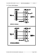
Page 46: ...Doc Ref No Q875 0143 ENG Issue 2 Met 30 Operating Manual 12 01 10 8 4 Printer Cable Diagrams File Name Q875 0143 ENG Iss2 Met30 Operating doc Page 44 of 58...

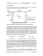
Page 47: ...DC screen described in the ADC Screen section of this manual Pressing the ESCAPE key will cause the current state to revert back to the initial bargraph screen Touching the DISPLAY key is equivalent t...

Page 48: ...not be available The figure above shows the graphics menu as ZRCFBP where the letters have the following meanings Z Zoom In Out R Rotate phase C Clear display F Flash mode B Bar graph display P Phase...

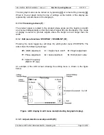
Page 49: ...on the previous plot may be re drawn A single press will result in a step of one scale interval Continual presses will cause increasingly larger steps 9 1 1 2 Rotate detection envelope R The phase an...

Page 50: ...mode of display is useful for product signals where the height is much larger than the width 9 1 2 Edit menu functions WCHPGN WCHPGNF 3F Pressing the menu toggle key will show the editing letter menu...

Page 51: ...g A single press will result in a step of one Continual presses will cause increasingly larger steps 9 1 2 4 Phase adjustment P The products phase angle setting will be increased by pressing or decrea...

Page 52: ...letters and use the S key for special characters Pressing each of these keys changes the characters displayed on the keyboard To amend the name move to the left or right with the and keys Press the M...

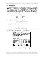
Page 53: ...yed from the operator s menu Test Product Print Exit Selecting Print will result in a display as follows Set up printer or PC on port A SELECT Press and the Display option will be shown Display Press...

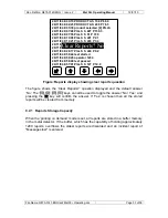
Page 54: ...200 P 76 3 26 11 04 8 05 39 product selected 2 PILLS 26 11 04 8 07 48 PILLS S 227 P 130 3 26 11 04 8 07 55 PILLS S 51 P 37 9 26 11 04 8 10 08 PILLS S 221 P 2 1 26 11 04 8 14 21 PILLS S 224 P 3 4 26 1...

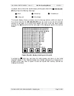
Page 55: ...26 11 04 8 57 01 PILLS S 127 P 12 8 Clear Reports No Figure Reports display showing clear reports question The figure shows the Clear Reports question displayed and the default answer No The keys can...

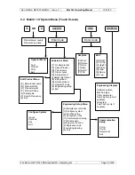
Page 56: ...roduct setup data Communication Setup Port A Port B Detector ID Exit Engineering displays Software version Machine type Timer parameter Syschek time only if configured Noise test Test Tacho only if co...

Page 57: ...counts Product setup data Engineering Setup Menu S Sample test reminder c Configure system v Vibration setup T Set system clock C Communication setup P Printer setup s Supervisor s code e Engineer s...

Page 58: ...ly cables are wired correctly If everything appears to be OK call Lock 10 3 Detects sample but false triggers There are many possible reasons for this below is a list of possible causes Components gui...

Page 59: ...ny metal that moves near to the aperture may be detected by the metal detector This could result in false triggering To prevent this there should be a metal free zone around the detector aperture i e...

Page 60: ...ed to the PSU and settings in the software 11 11 Test Sample When a metal detector is shipped by Lock a test sample is sent with it This is a small piece of metal embedded in plastic or a laminated ca...

Page 61: ...ority Drive Fitchburg MA 01420 6094 USA Tel 1 978 343 3716 800 227 5539 Fax 1 978 343 6278 LOCK INSPECTION SYSTEMS BV Daalderweg 17 4879 AX Etten Leur The Nederland Tel 31 0 76 5030 212 Fax 31 0 76 50...

Reviews: