60
12.11
CHECKING THE OPERATING HISTORY
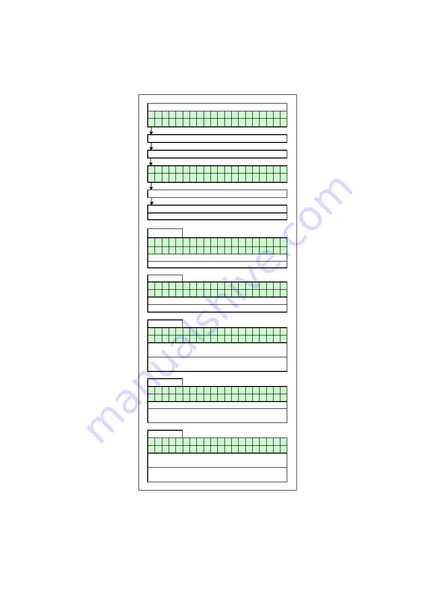
The following figure describes how to check the operating history of the boiler.
FIGURE 12.16
CHECKING THE OPERATING HISTORY
Operating screen:
H E A T I N G : S T A N D - B Y
> > > : 1 2 3 . 4
o
C ( 1 2 3 . 4
o
C )
Press [MENU]
Select "Operate" using [◄] & [►]
M a i n
M e n u
O p e r a t e
Press [◄] & [►] to browse through the 5 screens.
SCREEN:
1
O p e r a t
i n g
h i s t o r y
P o w e r O n
h r s
1 3 1 4 0 0
SCREEN:
2
h r s C h
T o t
1 0 0 0 0 0 0
h r s D h w
T o t
1 0 0 0 0 0 0
SCREEN:
3
h r s C h
< 5 0 %
1 0 0 0 0 0 0
h r s C h
= > 5 0 %
1 0 0 0 0 0 0
SCREEN:
4
h r s D h w
< 5 0 %
: 1 0 0 0 0 0 0
h r s D h w = > 5 0 %
: 1 0 0 0 0 0 0
SCREEN:
5
T i a 1 0 0 0 0 0 F i a
1 0 0 0 0 0
S s l 1 0 0 0 0 0 S s t
1 0 0 0 0 6
Bottom line:
Ssl
= Soft Starts last
Sst
= Soft Starts Total
Bottom line: Burner-on hours for DHW while the burner was firing at equal to or
more than 50% .
Top line: Burner-on hours for central heating while the burner was firing at less
than 50% .
Bottom line: Burner-on hours for central heating while the burner was firing at
equal to or more than 50% .
Top line: Shows the operating history menu is activated.
Press [MENU] or [ENTER] to exit. The unit will return to the operating screen.
Press [ENTER]
Top line: Total burner-on hours for central heating demand.
Bottom line: Total burner-on hours for DHW demand.
Top line:
Tia
= Total Ignition Attempts
Fia = Failed Ignition Attempts
Top line: Burner-on hours for DHW while the burner was firing at less than 50% .
Bottom line: Total number of hours that the boiler has been powered on for.
Summary of Contents for CP-M Series
Page 5: ...5 2 0 PRINCIPAL PARTS FIGURE 2 1 REMOVABLE COMPONENTS CP M 60...
Page 6: ...6 FIGURE 2 2 REMOVABLE COMPONENTS CP M 60 CONTINUED...
Page 8: ...8 FIGURE 2 3 REMOVABLE COMPONENTS CP M 80 CP M 100...
Page 9: ...9 FIGURE 2 4 REMOVABLE COMPONENTS CP M 80 CP M 100 CONTINUED...
Page 11: ...11 FIGURE 2 5 REMOVABLE COMPONENTS CP M 120...
Page 12: ...12 FIGURE 2 6 REMOVABLE COMPONENTS CP M 120 CONTINUED...
Page 14: ...14 FIGURE 2 7 REMOVABLE COMPONENTS CP M 150 CP M 180...
Page 15: ...15 FIGURE 2 8 REMOVABLE COMPONENTS CP M 150 CP M 180 CONTINUED...
Page 94: ...94...


