CHAPTER 7: OPERATION
7-9
ECOLOAD S2
4.4. Start a new machining
Conditions must be fulfilled before proceeding automatic sequence:
1. The lathe is not in AUTOMATIC mode.
2. The lathe chuck is open.
3. The lathe stopper must be positioned at the TOP CUT position.
4. The lathe program is already set properly.
5. The bar feeder is installed and anchored.
The bar stocks are put on the magazine.
6. All parameters are set properly.
7. The bar feeder has been properly set according to pneumatics, electrics and mechanics according to
bar stock dimension and machining conditions.
8. V channel is at 15° position (SR2 ON).
Steps to set automatic sequence:
1. Manually move the lathe stopper to TOP CUT position.
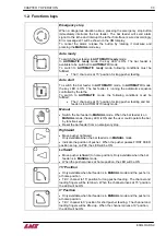
2. Press
until the long pusher moves back to home position (SR3 ON).
Press
to raise the V channel and tilt it to 0° position (SR1 ON) for loading a new bar.
Position the short pusher at feeding position.
3. Press
to move the short pusher forward for feeding the new bar out of bar feeder.
4. Press
key to return short pusher to home position (SR3 ON).
5. Press
to lower the V channel and tilt it to 15° position (SR2 ON).
Position the long pusher at feeding position.
6. Press
until the long pusher pushes the bar stock against the stopper.
Do not release till the chuck closes.
7. Close
lathe
chuck.
8. Switch the bar feeder into AUTOMATIC mode by pressing
and
in sequence.
The related LED will ON.
9. The long pusher moves back to home position (SR3 ON).
Manually do the bar preparation on the lathe.
10. Switch the lathe to auto mode.
Never switch the bar feeder into AUTOMATIC mode the chuck is open!!!
Never switch the lathe into AUTOMATIC mode before switching the bar feeder is in
AUTOMATIC mode.
Summary of Contents for Eco Load S2
Page 1: ...LNS SA 2534 Orvin Switzerland www LNS group com Instruction manual ENG 9 ECO 01 ...
Page 2: ......
Page 5: ...CHAPTER 1 BASIC NOTIONS 1 1 ECOLOAD S2 CHAPTER 1 BASIC NOTIONS ...
Page 12: ...1 8 CHAPTER 1 BASIC NOTIONS ECOLOAD S2 ...
Page 13: ...CHAPTER 2 TECHNICAL DATA 2 1 ECOLOAD S2 CHAPTER 2 TECHNICAL DATA ...
Page 17: ...CHAPTER 2 TECHNICAL DATA 2 5 ECOLOAD S2 2 3 Z axis retraction system ˋˆˊ ˊˋˊ ˌˊ ˉ ˁˈ ʳ ˆˇ ˈ ...
Page 19: ...CHAPTER 3 SETTING INTO OPERATION 3 1 ECOLOAD S2 CHAPTER 3 SETTING INTO OPERATION ...
Page 36: ...3 18 CHAPTER 3 SETTING INTO OPERATION ECOLOAD S2 ...
Page 37: ...CHAPTER 4 ELECTRICS 4 1 ECOLOAD S2 CHAPTER 4 ELECTRICS ...
Page 43: ...CHAPTER 4 ELECTRICS 4 7 ECOLOAD S2 4 2 Circuit diagram ...
Page 45: ...CHAPTER 4 ELECTRICS 4 9 ECOLOAD S2 5 2 PLC I O DIAGRAMS ...
Page 54: ...4 18 CHAPTER 4 ELECTRICS ECOLOAD S2 ...
Page 55: ...CHAPTER 5 PNEUMATICS 5 1 ECOLOAD S2 CHAPTER 5 PNEUMATICS ...
Page 57: ...CHAPTER 5 PNEUMATICS 5 3 ECOLOAD S2 2 PNEUMATIC CIRCUIT DIAGRAM ...
Page 62: ...5 8 CHAPTER 5 PNEUMATICS ECOLOAD S2 ...
Page 63: ...CHAPTER 6 GENERAL DESCRIPTION 6 1 ECOLOAD S2 CHAPTER 6 GENERAL DESCRIPTION ...
Page 77: ...CHAPTER 7 OPERATION 7 1 ECOLOAD S2 CHAPTER 7 OPERATION ...
Page 98: ...7 22 CHAPTER 7 OPERATION ECOLOAD S2 ...
Page 99: ...CHAPTER 8 TROUBLESHOOTING GUIDE 8 1 ECOLOAD S2 CHAPTER 8 TROUBLESHOOTING GUIDE ...
Page 109: ...CHAPTER 9 APPENDICES 9 1 ECOLOAD S2 CHAPTER 9 APPENDICES ...


