background image

5

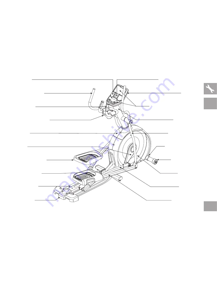
PIVOTING FOOT PADS

CRANK

INCLINE BRACKET

TOP CAP

GUIDE RAIL SET

SPEAKERS

WATER BOTTLE HOLDER

UPPER HANDLEBAR

PULSE GRIPS

REAR COVER

STABILIZER TUBE

POWER CORD SOCKET

MAIN FRAME

PEDAL ARM

IPOD/MP3 PLAYER POCKET

CONSOLE MAST

CONSOLE

BUTTONS AND DISPLAY WINDOWS

LOWER HANDLEBAR

LOWER LINK ARM

ls9.9e

Summary of Contents for LS12.9E

Page 1: ...Read the elliptical guide before using this owner s manual LS12 9E LS9 9E LS7 9E ELLIPTICAL OWNER S MANUAL ...

Page 2: ... at LIVESTRONG org INTRODUCTION Congratulations and thank you for your purchase of this LIVESTRONG elliptical Purchases of this product ensure that a minimum of 4M will go to the Lance Armstrong Foundation and the fight against cancer Whether your goal is to win races or simply enjoy a fuller healthier lifestyle a LIVESTRONG elliptical can help you attain it adding club quality performance to your...

Page 3: ...ses To prevent damage to the elliptical the assembly instructions must be reviewed and corrective actions should be taken Before proceeding find your elliptical s serial number located on the front stabilizer tube and enter it in the space provided below Also locate the model name which is next to the serial number ENTER YOUR SERIAL NUMBER AND MODEL NAME IN THE BOXES BELOW Refer to the SERIAL NUMB...

Page 4: ...L SET SPEAKERS WATER BOTTLE HOLDER UPPER HANDLEBAR PULSE GRIPS CONSOLE REAR COVER STABILIZER TUBE POWER CORD SOCKET MAIN FRAME PEDAL ARM IPOD MP3 PLAYER POCKET CONSOLE MAST TOUCH PAD PANEL AND DISPLAY WINDOWS LOWER HANDLEBAR LOWER LINK ARM LS7 9E ...

Page 5: ...AP GUIDE RAIL SET SPEAKERS WATER BOTTLE HOLDER UPPER HANDLEBAR PULSE GRIPS REAR COVER STABILIZER TUBE POWER CORD SOCKET MAIN FRAME PEDAL ARM IPOD MP3 PLAYER POCKET CONSOLE MAST CONSOLE BUTTONS AND DISPLAY WINDOWS LOWER HANDLEBAR LOWER LINK ARM LS9 9E ...

Page 6: ...RS WATER BOTTLE HOLDER UPPER HANDLEBAR PULSE GRIPS REAR COVER STABILIZER TUBE POWER CORD SOCKET MAIN FRAME PEDAL ARM IPOD MP3 PLAYER POCKET INCLINE LEVEL TOGGLES RESISTANCE LEVEL TOGGLES CONSOLE MAST CONSOLE BUTTONS AND DISPLAY WINDOWS LOWER HANDLEBAR LOWER LINK ARM LS12 9E ...

Page 7: ...wer Cord F F 9 Hardware Bags LS12 9E or F F 7 Hardware Bags LS7 9E LS9 9E UNPACKING Unpack the product where you will be using it Place the elliptical carton on a level flat surface It is recommended that you place a protective covering on your floor Never open box when it is on its side NOTE During each assembly step ensure that ALL nuts and bolts are in place and partially threaded in before com...

Page 8: ...pring washers b and 4 arc washers C BOLT A 30 mm Qty 4 SPRING WASHER B 15 mm Qty 4 ARC WASHER C 17 mm Qty 4 HARDWARE BAG 1 CONTENTS BOLTS A SPRING WASHERS B ARC WASHERS C STABILIZER TUBE MAIN FRAME BOLTS A SPRING WASHERS B ARC WASHERS C STABILIZER TUBE MAIN FRAME ALL MODELS LS7 9E shown LS9 9E LS12 9E shown ...

Page 9: ...h main frame as shown C Attach the guide rail set to the main frame using 4 bolts D 4 flat washers e and 4 tooth washers g TOOTH WASHER G 15 mm Qty 4 FLAT WASHER E 17 mm Qty 4 BOLT D 55 mm Qty 4 HARDWARE BAG 2 CONTENTS TOOTH WASHERS G FLAT WASHERS E GUIDE RAIL SET BOLTS D MAIN FRAME LS7 9E shown LS7 9E ...

Page 10: ...are bag 2 B Attach the guide rail set to the main frame using 4 bolts D 4 flat washers e and 4 tooth washers g TOOTH WASHER G 15 mm Qty 4 FLAT WASHER E 17 mm Qty 4 BOLT D 55 mm Qty 4 HARDWARE BAG 2 CONTENTS For Steps A B TOOTH WASHERS G FLAT WASHERS E GUIDE RAIL SET BOLTS D MAIN FRAME LS9 9E LS12 9E ONLY LS9 9E LS12 9E ...

Page 11: ... 4 bolts h 4 flat washers i 4 spring washers b and 4 nuts j SPRING WASHER B 15 mm Qty 4 FLAT WASHER I 16 mm Qty 4 BOLT H 35 mm Qty 4 NUT J Qty 4 HARDWARE BAG 2 CONTENTS For Step C GUIDE RAILS MAIN FRAME BOLTS H SPRING WASHERS B FLAT WASHERS I NUTS J LS9 9E LS12 9E ONLY LS9 9E LS12 9E ...

Page 12: ... onto the main frame and attach console mast to main frame using pre installed bolts D Slide wavy washer l over crank followed by pedal arm as shown Rest pedal arm wheel on guide rail E Attach the pedal arm to the crank using 1 flat washer k 1 spring washer b and 1 bolt M F Repeat steps D E on the opposite side of the elliptical BOLT M 20 mm Qty 2 SPRING WASHER B 15 mm Qty 2 FLAT WASHER K 20 mm Qt...

Page 13: ...asher k 1 handlebar cap 1 flat washer k 1 spring washer b and 1 bolt M D Repeat steps B C on the opposite side of the elliptical BOLT M 20 mm Qty 2 SPRING WASHER B 15 mm Qty 2 FLAT WASHER K 20 mm Qty 4 WAVY WASHER L 22 5 mm Qty 2 FLAT WASHER N 25 mm Qty 6 HARDWARE BAG 4 CONTENTS LS12 9E SHOWN BOLT M SPRING WASHER B FLAT WASHERS K FLAT WASHERS N CONSOLE MAST HANDLEBAR CAP LOWER HANDLEBAR WAVY WASHE...

Page 14: ...racket on bottom of lower handlebar NOTE Be sure to remove the zip tie on the link arm E Place Teflon washers P on both sides of the lower link arm While holding Teflon washers p slide lower link arm into bottom end of lower handlebar F Secure the joint with 1 flat washer e 1 spring washer b 1 bolt o and secure with 1 nut j G Repeat steps B F on the opposite side of the elliptical BOLT M 20 mm Qty...

Page 15: ...en hardware bag 6 B Slide right and left top cap over console mast and attach using 3 screws Q C Slide console mast boot around console mast and insert into top cap D Slide water bottle holder over console mast and attach using 2 screws R E Slide rear cap over rear stabilizer and attach using 2 screws q SCREW Q 15 mm Qty 5 SCREW R 15 mm Qty 2 HARDWARE BAG 6 CONTENTS LS12 9E SHOWN Note Be careful n...

Page 16: ... skip to next page A Open hardware bag 7 B Slide top cap and top cap rear cover over console mast and snap into place C Insert console mast boot over top cap and snap into place D Slide water bottle holder over console mast and attach using 2 screws S HARDWARE BAG 7 CONTENTS SCREW S 15 mm Qty 2 LS7 9E SHOWN Note Be careful not to pinch any wires while tightening screws ...

Page 17: ...le mast using 4 bolts T D Slide upper handlebars onto lower handlebars and align notch with tab making sure handlebars are joined together completely Secure upper handlebars to lower handlebars using pre attached set screws E LS12 9E ONLY Connect the handlebar wires from the upper handlebar to the wires from the console mast F Repeat step D E on other side ASSEMBLY STEP 8 BOLT T 12 mm Qty 4 HARDWA...

Page 18: ...ndlebar Attach aero hand grip to the upper handlebar using 2 bolts t Note Be careful not to pinch any wires C Repeat on other side D Snap right handlebar covers over handlebars and attach using 4 screws q E Repeat on other side LS12 9E ASSEMBLY STEP 9 BOLT T 15 mm Qty 4 SCREW Q 15 mm Qty 8 HARDWARE BAG 9 CONTENTS LS12 9E ONLY Note Be careful not to pinch any wires while attaching parts LS9 9E LS12...

Page 19: ... and programming The BASIC OPERATION section in the elliptical guide has instructions for the following LOCATION OF THE Elliptical POWER GROUNDING INSTRUCTIONS FOOT POSITIONING MOVING the elliptical LEVELING the elliptical POWER MANUAL INCLINE OPERATION Using the HEART RATE function ...

Page 20: ... MOUNTAIN WEIGHT LOSS CONSTANT WATTS 1 2 3 5 6 7 4 8 9 10 11 13 14 15 12 16 LS7 9E CUSTOM PROGRAM 1 CUSTOM PROGRAM 2 SELECT PROGRAM ENTER CHANGE DISPL AY P R O G R A M M I N G C O N T R O L S STOP HOLD TO RESET START QUICK START L E V E L L A B B G H F E C J I F M D N O K K LS7 9E ...

Page 21: ...stance level more quickly G Select program press to select your desired program H Custom 1 2 press to select your custom 1 or 2 program LED will illuminate I Enter used to confirm and adjust program settings J Change display press to change display feedback during workout K Speakers music plays through speakers when your CD mp3 player is connected to the console L Audio in jack plug your CD mp3 pl...

Page 22: ...22 LS9 9E CALORIES HEART RATE SPEED WATTS RPM ENTER BACK PROGRAMMING CONTROLS CHANGE DISPLAY LS9 9E START QUICK START STOP HOLD TO RESET DISTANCE TIME L A B G H F C D E I F M F N O K K J ...

Page 23: ...set level H Set incline press to set incline after pressing a quick key number 0 100 increments of 5 I Set resistance press to set resistance level after pressing a quick key number 20 levels increments of 1 J Programming button used to select program level and time and other options Press to change display feedback during workout ENTER is used to confirm a selection BACK is used to move back in p...

Page 24: ...ATE SPEED WATTS RPM ENTER BACK PROGRAMMING CONTROLS LS12 9E START QUICK START STOP HOLD TO RESET CHANGE DISPL AY F I T N E S S J O U R N A L S Y S T E M PRESS TO SCROLL DISTANCE TIME CLOCK DATE A B K L G H C D E I O F P Q M M J N ...

Page 25: ...ck key number 0 100 increments of 5 I Set resistance press to set resistance level after pressing a quick key number 20 levels increments of 1 J Programming button used to select program level and time and other options Press to change display feedback during workout ENTER is used to confirm a selection BACK is used to move back in program setup K LIVETRACK BUTTON press to activate deactivate LIVE...

Page 26: ...art rate displayed when contact is made with both pulse grips DISTANCE TIME SPEED WATTS CALORIES HEART RATE MANUAL REVERSE TRAIN INTERVALS MOUNTAIN WEIGHT LOSS CONSTANT WATTS CALORIES HEART RATE SPEED WATTS RPM DISTANCE TIME CLOCK DATE LS7 9E DISPLAYS LS9 9E LS12 9E DISPLAYS Level Shows the current level of resistance Will be displayed in the alphanumeric window INCLINE LS9 9E LS12 9E ONLY Shown a...

Page 27: ...g out The time will count up from 0 00 the resistance level will default to level 1 B SELECT A program 1 Select a program using the select program key Press enter to confirm 2 Adjust the time using the keys 3 Press start or enter to begin workout LS7 9E GETTING STARTED 1 Check to make sure no objects are nearby that will hinder the movement of the elliptical 2 Plug in the power cord and turn the e...

Page 28: ...g and press enter on the programming button 2 Select a level using and press enter 3 Set time using and press enter 4 Press start or enter to begin the program Note if you press start before pressing enter the program will begin and counts up from 0 00 for the Manual P1 and Constant Watts P4 programs and count down from 30 00 for all other programs The level defaults to 1 LS9 9E GETTING STARTED 1 ...

Page 29: ...ter C SELECT A program 1 Select a program using and press enter on the programming button 2 Select a level using and press enter 3 Set time using and press enter 4 Press start or enter to begin the program Note if you press start before pressing enter the program will begin and counts up from 0 00 for the Manual P1 and Constant Watts P4 programs and count down from 30 00 for all other programs The...

Page 30: ...goal with 14 difficulty levels to choose from 5 Mountain Simulates climbing mountains by increasing and decreasing the resistance Time based goal with 15 difficulty levels to choose from 6 Constant Watts 1 Select Constant Watts program using and press enter on the programming button 2 Set time using and press enter 3 Select desired watts using and press enter 4 Press start or enter to being the pr...

Page 31: ...rt rate within 5 beats of the target number you selected at the beginning of the program If there is no heart rate detected the unit will not change resistance levels up or down If your heart rate is 25 beats over your target zone the program will shut down LS9 9E LS12 9E PROGRAM INFORMATION 100 75 60 BEATS PER MINUTE 20 25 30 35 40 45 50 55 60 65 AGE T A R G E T Z O N E 120 117 114 111 108 105 10...

Page 32: ...Press enter to confirm 3 Set each resistance incline profile by using and press enter Repeat for all 15 resistance incline profiles NOTE You may go back to the previous segment by pressing back on the programming button 4 Press start to begin LS9 9E LS12 9E PROGRAM INFORMATION Date and clock setup LS12 9E only 1 Enter Setup Mode Press and hold 1 and 2 BUTTONS for 3 5 seconds 2 Use the ENTER button...

Page 33: ...e traveled calories burned or your overall pace you ll be able to quickly and easily see the progress you ve made You can also track your workout totals By following your total number of workouts distance and calories you ll be able to see just how far you have come Read further to see how LIVETRACK can help motivate you to enhance your performance SETUP To activate LIVETRACK fitness journal syste...

Page 34: ...is option allows you to view your accumulated data from your last workout The current workout becomes the last workout once a program has ended or the console has been reset The following information will be shown in each display window Time total time of last workout Calories total calories burned of last workout Watts average watts of last workout Distance total distance of last workout Speed av...

Page 35: ...al accumulated data The following information will be shown in each display window Time total accumulated time Note if time is greater than 59 59 the time will no longer display minutes and will display hours only Calories average calories burned Watts average watts Distance total accumulated distance Speed average speed RPM average RPM Weekly goal setup 1 Select user 1 or user 2 2 Press the LIVET...

Page 36: ... the top of the console and the headphone jack on your CD mp3 player 2 Use your CD mp3 player buttons to adjust song settings 3 Remove the audio adaptor cable when not in use 4 If you don t want to use the speakers you can plug your headphones into the audio out jack at the bottom of the console ...

Page 37: ...37 LIMITED HOME USE WARRANTY ...

Page 38: ...on of the original owner EXCLUSIONS AND LIMITATIONS Who IS covered The original owner and is not transferable What IS covered Repair or replacement of a defective motor electronic component or defective part and is the sole remedy of the warranty What IS NOT covered Normal wear and tear improper assembly or maintenance or installation of parts or accessories not originally intended or compatible w...

Page 39: ...rized service technician All repairs attempted by you on your fitness equipment are undertaken AT YOUR OWN RISK and Manufacturer shall have no liability for any injury to the person or property arising from such repairs SERVICE RETURNS In home service is available within 150 miles of the nearest authorized repair center Mileage beyond 150 miles from an authorized service center is the responsibili...

Page 40: ...E COVERED BY ONE OR MORE PATENTS OR PATENTS PENDING US 5540637 US 5573480 US 5813949 US 5924962 US 5938567 US 6135927 US 6149551 US 7316633 CN 99808486 7 TW 364373 TW 371899 DO NOT RETURN TO THE RETAILER if you have any problems during assembly or if parts are missing Note Please read the troubleshooting section in the elliptical guide before contacting Customer Tech Support CUSTOMER TECH SUPPORT ...

Reviews: