


7
102.3 “Normally OFF” Loads
CAUTION:
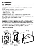
To use this product with normally off lighting loads requires rewiring the circuit board to bypass an internal
relay. This process should only be performed by qualified personnel. Refer to Fig. 102-1.
For
120VAC
Operation:
• Remove the black wire lead from FT16, remove the “push on” connector, and strip the end.
• Remove the red wire lead from FT14, remove the “push on” connector, and strip the end.
• Join them using an approved mechanical connector.
OR
For
277VAC
operation:
• Remove the orange wire lead from FT17, remove the “push on” connector, and strip the end.
• Remove the orange wire lead from FT15, remove the “push on” connector, and strip the end.
• Join them using an approved mechanical connector.
Connect utility and load to appropriate terminal blocks and ensure the input, output, and chassis are grounded.
102.4 Externally Switched Loads
For
120VAC
Operation:
• Disconnect the black wire from FT22.
• Remove the terminal and strip the wire.
• Connect to unswitched 120VAC power supply.
• Connect switched 120VAC power to the 120V input connection of the input terminal block (pins not numbered).
OR
For
277VAC
operation:
• Disconnect the orange wire from FT23.
• Remove the terminal and strip the wire.
• Connect to unswitched 277VAC power supply.
• Connect switched 277VAC power to the 277V input connection of the input terminal block (pins not numbered).
Connect utility and load wires to appropriate terminal blocks and ensure the input, output, and chassis are grounded.
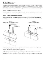
103. Installing The Batteries and DC Wiring
103.1 General Precautionary Measures
A qualified electrician who is familiar with battery systems and required precautions must install and service the
batteries. Any battery used with this unit shall comply with the applicable requirements for batteries in the standard
for emergency lighting and power equipment, UL 924. Cabinets are designed to be used with, and batteries must
be replaced with identical cells or a Dual-Lite approved equivalent. If using substitute batteries not supplied by Dual-
Lite, the unit’s UL listing will be void, and the equipment may fail to perform properly. The installation must conform to
national and local codes as well. Keep unauthorized personnel away from batteries.
Wear protective clothing, eye-wear, rubber gloves and boots. Batteries contain corrosive acids or caustic alkalis and
toxic materials and can rupture or leak if mistreated. Remove rings and metal wristwatches or other metal objects and
jewelry. Don’t carry metal objects in pockets where the objects can fall onto the batteries or into the LiteGear inverter
system.
Tools must have insulated handles so that they will not short battery terminals. Do not allow a tool to short a battery
terminal to another battery terminal or to the cabinet at any time. Do not lay tools or metal parts on top of the batteries,
and do not lay any objects where they could fall onto the batteries or into the cabinet.
Install the batteries as shown on the battery wiring diagram provided in this manual with the cables provided. When
connecting cables, never allow a cable to short across a battery’s terminals, the string of batteries, or to the cabinet.
Keep the cables away from any sharp metal edges.
Install the battery cables so they cannot be pinched by the LiteGear inverter system’s cover.
Where conductors may be exposed to physical damage, protect conductors in accordance with NEC requirements.


