LiteGear Inverter Power System Installation Instructions And User Manual Download Page 6

6

101.2  AC Wiring Preparations

If not previously done, remove knockouts for AC Input and AC Output in the LiteGear inverter system and install input 
and output conduits per section 100.2 

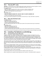
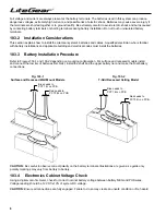
101.3  AC Input Voltage Selection

The battery charger transformer has two input leads: 
 

black = 120VAC 

orange = 277VAC

Select proper AC input lead for the application.
Refer to Fig. 102-1.

For 

120VAC

 input:

•  Black – Connect to FT22
•  Orange – Remove “push on” connector and cap off using appropriate mechanical  
  connector

OR

For 

277VAC

 input:

•  Orange – Connect to FT23
•  Black - Remove “push on” connector and cap off using appropriate mechanical  
  connector

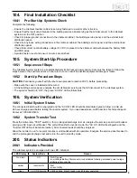
101.4  AC Output Voltage Selection 

Refer to Fig. 102-2 

For 

120VAC

 output:

•  Install 120VAC fuse into holder and install fuse holder in bracket
•  Discard 277VAC fuse and install fuse holder in bracket

OR

For 

277VAC

 output:

•  Install 277VAC fuse into holder and install fuse holder in bracket
•  Discard 120VAC fuse and install fuse holder in bracket

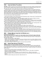
101.5  AC Output Wattage Selection 

Refer to Fig. 102-3 

For loads less than 

36 Watts

:

•  Remove jumper connected between J1 and J2 on the standoff  
  electronics board
•  If load wattage is increased later, then jumper should be reapplied.  
  Otherwise, unit will fail to provide output voltage.

OR

For loads greater than or equal to 

36 Watts

:

•  Proceed to Section 102

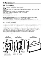
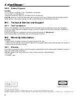
102.  Load Configuration Wiring Options

102.1  AC Input and AC Output Connections

CAUTION:

 Torque all terminal block connections to 4.4 to 5.3 in-lb. (0.5 to 0.6 Nm.)  Failure to do so may create an 

unsafe condition or fire hazard. Only "Normaly ON" or "Normally OFF" or "Externally Switched" loads can be selected.

102.2  “Normally ON” loads

Connect utility and load to appropriate terminal blocks per Fig. 102-1 and ensure the input, output, and chassis are 
grounded.

Fig. 102-2

Fig. 102-1

COM OUT

COM IN

120V IN

277V IN

120V OUT

277V OUT

277V 

IN

120V 

IN

COM 

IN

COM 

OUT

120V 

OUT

277V 

OUT

FT16

FT14

FT17

FT15

FT23

FT22

FT20

FT21

FT19

FT18

J2

J1

JUMPER

Fig. 102-3

JUMPER

Summary of Contents for Inverter Power System

Page 1: ...Installation Instructions and User Manual For 100 Watt Inverter Power System...

Page 2: ...Battery acid can cause burns to skin and eyes If acid is spilled on skin or in the eyes flush with fresh water and contact a physician immediately 6 Equipment should be mounted in locations where it...

Page 3: ...re 8 103 4 Electronics Cabinet Voltage Check 8 104 Final Installation Checklist 9 104 1 Pre Start Up Systems Check 9 105 System Start Up Procedure 9 105 1 Sequence of Steps 9 105 2 Start Up Procedure...

Page 4: ...it and prevent it from operating If additional or larger entry points are needed use a chassis punch to enlarge the appropriate knockout Do not add unnecessary knockouts For surface and recessed cabin...

Page 5: ...r inverter system AC line service and batteries The electrician must install the AC line service according to local state and NEC codes and must be familiar with batteries and battery installation Bef...

Page 6: ...fuse holder in bracket Discard 120VAC fuse and install fuse holder in bracket 101 5 AC Output Wattage Selection Refer to Fig 102 3 For loads less than 36 Watts Remove jumper connected between J1 and...

Page 7: ...attery systems and required precautions must install and service the batteries Any battery used with this unit shall comply with the applicable requirements for batteries in the standard for emergency...

Page 8: ...nstallation Procedure Refer to Figures 103 1 and 103 2 depending on mounting configuration For surface and recessed models install and connect the low tier of batteries first Next install the shelf an...

Page 9: ...aken to follow the steps below in their exact sequence Failure to do so can result in possible equipment damage or failure 105 2 Start Up Procedure Steps CAUTION Familiarize yourself with the shut dow...

Page 10: ...every 60 to 90 days CAUTION The batteries will be damaged and the warranty voided if the batteries are not routinely recharged NOTE To turn power back on follow the System Start up Procedure outlined...

Page 11: ...s or repairing battery connections follow the procedure in this manual to shut down the LiteGear inverter system and remove both AC and DC input power Full voltage and current are always present at th...

Page 12: ...established for LiteGear technical assistance 1 800 848 6439 Service representatives are available during normal working hours EST 302 Warranty Information CAUTION Lengthy storage of batteries will ca...

Reviews: