LiteGear Inverter Power System Installation Instructions And User Manual Download Page 4

4

100.  Installation 

100.1  General Installation Requirements

CAUTION:


LiteGear cabinets are very heavy. Check to assure that the chosen location is capable of safely bearing the load.

Cabinet Size

Surface/Recessed 14"W x 18.125"H x 4.25"D (35.6cm W x 46cm H x 10.8cm D)
Ceiling 23.85"W x 10.55H x 7.0"D (60.58cm W x 26.80cm H x 17.78cm D)

Weight (including batteries)

•  Surface Wall Mount Units 

43 lbs

•  Recessed Wall Mount Units  

45 lbs

•  Recessed Ceiling Mount Units 

41 lbs 

Install the LiteGear inverter system in a clean, cool, dry place with normal ventilation for human habitation. 
LiteGear inverter systems are UL Listed for 20°C to 30°C (+68°F to +86°F) operation. 
Battery performance and service life is maximized if the operating temperature is maintained at 25°C (77°F). 
The air around the unit must be clean, dust-free, and free of corrosive chemicals or other contaminants. Do not place 
the LiteGear inverter system or batteries in a sealed room or container. 

100.2  Cabinet Installation

CAUTION: 

Do not drill into the cabinet; drill filings may damage the unit and prevent it from operating. If additional or larger entry 
points are needed, use a chassis punch to enlarge the appropriate knockout. Do not add unnecessary knockouts. 

For surface and recessed cabinets remove the electronics plate by removing the four nuts holding it in place. All units 
should be mounted with the batteries removed. 
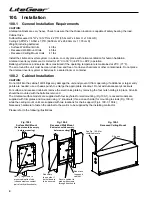
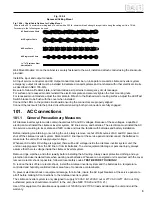
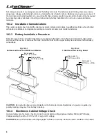
The LiteGear surface models are supplied with four keyholes for wall mounting (Fig 100-1); recessed models are 
supplied with trim plates and mounted using ¼” knockouts (three on each side) for mounting to studs (Fig. 100-2); 
while the ceiling mount units are supplied with two locations for chain support (Fig’s. 100-3, 100-4). 
Necessary hardware to fasten the cabinet to the wall is to be supplied by the installing contractor. 

Please refer to the following illustrations.

Fig. 100-1  

Surface Wall Mount

(Cabinet should be empty  

before mounting)

Use 

1

/

4

" lag screws to  

mount cabinet to studs 
(choose most convenient  
pair of vertical knockouts)

Fig. 100-2 

Recessed Wall Mount

(Cabinet should be empty  

before mounting)

Add shims 
to one side if 
both sides are 
to be secured

Add brace 
to support 
cabinet

Secure cabinet to 
studs with screws 
through knockouts

See Fig. 100-4 for 
chain/cable note

S hooks

Fig. 100-3

Recessed Ceiling Mount

Summary of Contents for Inverter Power System

Page 1: ...Installation Instructions and User Manual For 100 Watt Inverter Power System...

Page 2: ...Battery acid can cause burns to skin and eyes If acid is spilled on skin or in the eyes flush with fresh water and contact a physician immediately 6 Equipment should be mounted in locations where it...

Page 3: ...re 8 103 4 Electronics Cabinet Voltage Check 8 104 Final Installation Checklist 9 104 1 Pre Start Up Systems Check 9 105 System Start Up Procedure 9 105 1 Sequence of Steps 9 105 2 Start Up Procedure...

Page 4: ...it and prevent it from operating If additional or larger entry points are needed use a chassis punch to enlarge the appropriate knockout Do not add unnecessary knockouts For surface and recessed cabin...

Page 5: ...r inverter system AC line service and batteries The electrician must install the AC line service according to local state and NEC codes and must be familiar with batteries and battery installation Bef...

Page 6: ...fuse holder in bracket Discard 120VAC fuse and install fuse holder in bracket 101 5 AC Output Wattage Selection Refer to Fig 102 3 For loads less than 36 Watts Remove jumper connected between J1 and...

Page 7: ...attery systems and required precautions must install and service the batteries Any battery used with this unit shall comply with the applicable requirements for batteries in the standard for emergency...

Page 8: ...nstallation Procedure Refer to Figures 103 1 and 103 2 depending on mounting configuration For surface and recessed models install and connect the low tier of batteries first Next install the shelf an...

Page 9: ...aken to follow the steps below in their exact sequence Failure to do so can result in possible equipment damage or failure 105 2 Start Up Procedure Steps CAUTION Familiarize yourself with the shut dow...

Page 10: ...every 60 to 90 days CAUTION The batteries will be damaged and the warranty voided if the batteries are not routinely recharged NOTE To turn power back on follow the System Start up Procedure outlined...

Page 11: ...s or repairing battery connections follow the procedure in this manual to shut down the LiteGear inverter system and remove both AC and DC input power Full voltage and current are always present at th...

Page 12: ...established for LiteGear technical assistance 1 800 848 6439 Service representatives are available during normal working hours EST 302 Warranty Information CAUTION Lengthy storage of batteries will ca...

Reviews: