background image

  ISO 9001 CERTIFIED                                                             

www.liteputer.com.tw


23 

Lite-Puter 

DP-E500[EUM-B] 


STEP-2    Press

or

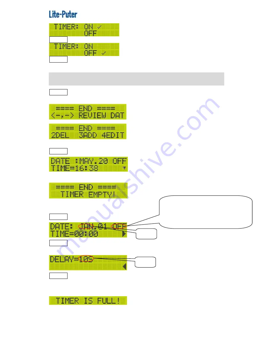
to select ON or OFF. 


STEP-3    After setting, press

ENT

to save or press

FCN

to exit. 


F8


EDIT TIMER 

STEP-1    On the main page, press

FCN

to enter the main menu and press

or

to select F8 EDIT TIMER. Press

ENT

and LCD displays, 


2DEL: Delete timer        3ADD: Add timer      4EDIT: Edit timer 

STEP-2    Press

or

to review all the timer. 


If there is no timer, LCD displays, 


Add Timer 

STEP-1    Press

3

to add a timer. 


STEP-2    Press

or

to select DATE, TIME, WDAY, MODE, SEQUENCE, 

FADE TIME and DELAY TIME; press

or

to adjust the value. 


STEP-3    After setting, press

ENT

to save or press

FCN

to exit.


Repeat STEP-1~STEP-3 to add more timer. 

When the timer record is full, LCD will display, 


For example,   
SEQ 2 will be call out on 16:38 every Monday, Thursday and the mode is 1, 
fade time is 3s and delay time is 3s. After setting, LCD displays, 

Blink   

Blink 

DATE is OFF that means timer’s date setting 

is useless. 

DATE  is  ON  that  means  timer  will  be 

executed on date. 

Summary of Contents for DP-E500

Page 1: ...ISO 9001 CERTIFIED www liteputer com tw 1 Lite Puter DP E500 EUM B DP E500 Ethernet to DMX Interface User Manual Lite Puter Enterprise Co Ltd Website www liteputer com tw Email sales liteputer com tw...

Page 2: ...F10 SET MAC 15 F11 ABOUT ME 15 2 1 2 Memory Initialization 15 2 1 3 Key Lock Unlock 16 2 1 4 Other 16 2 1 Work with RGB LED Control Software 17 2 2 1 Main Menu 18 F1 CALL SEQ 18 F2 MODIFY CH 19 F3 ED...

Page 3: ...ISO 9001 CERTIFIED www liteputer com tw 3 Lite Puter DP E500 EUM B 2 3 2 Memory Initialization 31 2 3 3 Key Lock Unlock 31 2 3 4 Other 32 2 4Control Software Shift 32 Limited Warranty 33...

Page 4: ...tion according to each control software After saving the data on DP E500 it can work alone 2 DMX 512 outputs for control up to 1204 channels Large memory for save scene timer and channel setting Chase...

Page 5: ...ite Puter DP E500 EUM B 1 3 Dimension 1 4 Function 1 LCD screen 2 Link and data indicator 3 Function button 4 Number button and indicator 5 IR receiver 6 DMX port 7 Ethernet port 8 DMX port 9 Power sw...

Page 6: ...ISO 9001 CERTIFIED www liteputer com tw 6 Lite Puter DP E500 EUM B 1 5 System Diagram Diagram 1 EDX DP E500 EDX 610 Control Panel IR Controller Ethernet Signal EDX Signal...

Page 7: ...ISO 9001 CERTIFIED www liteputer com tw 7 Lite Puter DP E500 EUM B Diagram 2 DMX DX 1220 DP E500 Ethernet Signal DMX Signal...

Page 8: ...hen DP E500 work with Home Lighting software its DMX1 port sent DMX 512 signal to the controller and DMX2 port receive the signal from the ECP control panel The max control channel quantity is 512 Sys...

Page 9: ...r to select the scene no press 1 to continue or press 2 to quit Press 1 and LCD displays STEP 4 Press or to select the channel no and or to adjust the dimming value STEP 5 After setting press ENT and...

Page 10: ...to enter the function and LCD displays STEP 2 Press or to select the scene no press 1 to continue or press 2 to quit Press 1 and LCD displays STEP 3 Press or to select the scene no again or press or...

Page 11: ...dd Timer STEP 1 Enter F3 1 and press 3 to add a timer STEP 2 Press or to select month day and schedule no and press or to adjust the value STEP 3 After setting press ENT to save or press FCN to quit R...

Page 12: ...to save or press FCN to exit 4 WEEK PTH STEP 1 Select F3 4 and press ENT and LCD displays STEP 2 Press or to select the week day press or to select the schedule no STEP 3 After setting press ENT to s...

Page 13: ...rearrange the DMX address order one channel no to several channel address DMX address 1 CH 001 DMX address 2 CH 001 DMX address 13 CH 001 DMX address 27 CH 001 DMX address 139 CH 001 DMX address 508 C...

Page 14: ...he channel is correspond to each DMX address exactly STEP 3 After setting press ENT to save or press FCN to exit F8 MODIFY CLOCK STEP 1 On the main page press FCN to enter the main menu and press or t...

Page 15: ...LCD displays STEP 2 Press or to select the byte and press or to adjust the value STEP 3 After setting press ENT to save or press FCN to exit F11 ABOUT ME On the main page press FCN to enter the main...

Page 16: ...or 3 seconds to unlcok the key and LCD displays 2 1 4 Other A When the DP E500 is working alone LCD displays DP E500 s IP address is 192 168 2 67 B When the DP E500 is working with the control softwar...

Page 17: ...rol Software When DP E500 s working with RGB LED control software DP E500 will receive Ethernet signal and its DMX1 DMX 2 port will send DMX 512 signal to control the LED devices the max control chann...

Page 18: ...the main menu STEP 2 Press or to select F1 CALL SEQ and press ENT and LCD displays STEP 3 Press or to select the SEQ no After setting press 1 to save and press 2 to exit Notice 1 When the SEQ OFF and...

Page 19: ...lue and save the setting to any scene Notice After enter this function all the SEQ will stop and the output will be the current step s scene All the channel s dimming value setting will be output imme...

Page 20: ...utput immediately STEP 1 On the main page press FCN to enter the main menu and press or to select F3 EDIT SCENE Press ENT and LCD displays STEP 2 Press or to select the scene no and press 1 to continu...

Page 21: ...and LCD displays STEP 3 Press or to select the STEP no and press or to select the scene no Notice If the any step s correspond to SC it means the following steps after this one will be useless For exa...

Page 22: ...er setting press ENT to save or press FCN to exit 2 SEQ001 SEQ512 Setting STEP 3 After selecting SEQ001 SEQ512 press 1 and LCD displays STEP 4 Press or to select FADE TIME DELAY TIME MODE SELECT and F...

Page 23: ...here is no timer LCD displays Add Timer STEP 1 Press 3 to add a timer STEP 2 Press or to select DATE TIME WDAY MODE SEQUENCE FADE TIME and DELAY TIME press or to adjust the value STEP 3 After setting...

Page 24: ...e SEQ 2 will be call out on 16 38 every Monday Thursday and May 20 And the mode is 1 fade time is 3s and delay time is 3s After setting LCD displays When the DATE is ON the DATE setting MAY 20 will be...

Page 25: ...channel control several DMX address second rearrange the DMX address order one channel no to several channel address DMX address 1 CH 001 DMX address 2 CH 001 DMX address 13 CH 001 DMX address 27 CH...

Page 26: ...P 1 On the main page press FCN to enter the main menu and press or to select F11 SET IP Press ENT and LCD displays STEP 2 Press or to select the byte and press to adjust the value STEP 3 After setting...

Page 27: ...nitialization STEP 1 After switching off hold FCN and OFF at the same time then switch DP E500 on till LCD displays Press 1 to start the initialization or press 2 to skip STEP 2 Press 1 to initializa...

Page 28: ...nu lock unlock function is useless 2 2 6 Other A When the DP E500 is working alone LCD displays DP E500 s IP address is 192 168 2 67 B When the DP E500 is working with the control software LCD display...

Page 29: ...2 3 Work with Lighting Control Software When DP E500 work with Lighting Control Software it will send DMX and EDX signal to control the devices System Diagram Work with Lighting Control Software DP E...

Page 30: ...select the byte and press or to adjust value STEP 3 After setting press ENT to save or press FCN to exit Notice Please make sure that the network don t have same IP F2 SET MAC STEP 1 On the main page...

Page 31: ...ss FCN to enter the main menu and press or to select F4 ABOUT ME Press ENT and LCD displays 2 3 2 Memory Initialization STEP 1 After switching off hold FCN and OFF at the same time then switch DP E500...

Page 32: ...ntrol Software Shift DP E500 can work with 3 control software Lighting Control Home Lighting and RGB LED Control Use can shift the control software by 1 When DP E500 working with PC it will shift to t...

Page 33: ...deliver the product to local distributors or to Taipei headquarters 4 The warranty does not cover a Any fault caused by false usage imprudence collision inadequate installation or adjustment insuffici...

Page 34: ...w liteputer com tw E mail sales liteputer com tw Shanghai Factory Lite Puter Technology Shanghai Co Ltd Address Building B5 No 298 Lane 3509 Hongmei S Road Shanghai China Zip Code 201108 Tel 86 21 544...

Reviews: