background image

1/38 


OPERATING MANUAL 

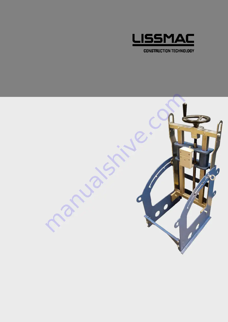
CORE DRILL STAND 

CDR 350 


LISSMAC Maschinenbau GmbH 
Lanzstrasse 4 
D-88410 Bad Wurzach 
Tel49 (0) 7564 / 307-0 
T49 (0) 7564 / 307-500 
[email protected] 
www.lissmac.com 

Summary of Contents for CDR 350

Page 1: ...1 38 OPERATING MANUAL CORE DRILL STAND CDR 350 LISSMAC Maschinenbau GmbH Lanzstrasse 4 D 88410 Bad Wurzach Telephone 49 0 7564 307 0 Telefax 49 0 7564 307 500 lissmac lissmac com www lissmac com...

Page 2: ...2 38...

Page 3: ...307 0 Fax 49 0 7564 307 500 lissmac lissmac com www lissmac com Original operating manual Status 08 2020 Passing on and duplication of this operating manual in any form as well as the use of the conte...

Page 4: ...rous situation If the situation is not avoided fatal or serious injuries can result The danger symbol can specify the endangerment CAUTION This signal word designates a dangerous situation If the situ...

Page 5: ...e work clothes and wash dusty clothes Attachment points for crane transport Danger through suspended loads Danger of cuts and amputation through rotary cutting tools Crushing danger for hands Highly f...

Page 6: ...ust gases Danger of crushing through unintended rolling away or slipping Danger of crushing through falling Danger of crushing for hands and fingers No use by unauthorized persons Instructions for avo...

Page 7: ...contained therein This applies among others to the following work Work including the setting up of the machine error search when executing work removal of wastes as consequence of drilling work machi...

Page 8: ...8 38 Notes...

Page 9: ...e 15 1 5 2 Dust 16 1 5 3 Noise 16 1 5 4 Exhaust gases 16 1 6 Transport 16 1 7 Packing and storage 16 1 8 Environmental protection 16 1 9 Disposal 17 2 Machine description 18 2 1 Core drill stand for c...

Page 10: ...drilling via the hand crank wheel which can be operated vertically and horizontally The feed of the support can be controlled exactly via the 1 1 direct translation as well as a trapezoidal Precise su...

Page 11: ...hile observing the operating manual In particular immediately remove faults which can impair safety or have them removed Intended use The LISSMAC core drill stands serves as a guidance and fastening a...

Page 12: ...heck safety and danger conscious working of the personnel while observing the operating manual Always use the necessary and prescribed personal protection equipment Observe all safety and danger notes...

Page 13: ...sh persons who do not work on the machine from the work area If necessary close off the work area The operators must ensure with all movements of the device that he does not endanger himself and other...

Page 14: ...drill motors and diamond drill bits permitted for this which are approved for the corresponding core drill stand The maximum diamond drill bit diameter must be observed Check the core drill stand for...

Page 15: ...ler than the nominal speed of the machine may not be used 1 4 5 Moving the core drill stand Movement of the core drill stand may only be made in a de energized state and when the tool is standing stil...

Page 16: ...e drill motor must be switched off even with a slight change of location 1 7 Packing and storage In order to ensure sufficient protection during dispatch and transport the machine and its components w...

Page 17: ...ticular if malfunctions occur please disable the worn out device Disposing of the device according to the environmental regulations valid in your country Electrical waste may not be disposed together...

Page 18: ...d wheel for feed Pos 6 Fastening of the clamping set Pos 2 Attachment point of the crane Pos 7 Fastening of the peg Pos 3 Guide tube Pos 8 Reception for the drill motor Pos 4 Height adjustment spindle...

Page 19: ...assembly by means of screw connection Feed 1 1 Angle bores 90 45 Fastening Clamping set pegs excavator shovel option Dimension L W H base frame 585 435 925 Weight in kg base frame 39 kg The technical...

Page 20: ...ntional position changes of the machine during transport Only transport the machine in transport position Secure the machine via suitable attachment points Use suitable lashing means Observe the presc...

Page 21: ...nly insert the core drill motor in a switched off state Implement the assembly with 2 persons Use gloves motor parts can be very hot after operation Sequence The motor is off Lock the inclination adju...

Page 22: ...be only be moved in the transport position Sequence The motor is off Tighten the inclination adjustment Remove the water supply Hang the drill stand into the crane lug with a slinging means with suff...

Page 23: ...ed on squared timber or a pallet and is secured against rolling away with wedges and the drill stand is securely fixed on the pipe with the tensioning strap CAUTION Danger of crushing through falling...

Page 24: ...y Some soils do not permit reliable fastening with pegs too soft or too rocky In principle we recommend in principle the use of the clamping set if possible If possible always create bores outside of...

Page 25: ...th the use of large drill bit diameters the assembly of a extension base is necessary The front cross member of the base frame is omitted The extension base is fastened to the base frame with the scre...

Page 26: ...f cuts and crushing setting up and moving Serious injury through a rotating drill bit or slipping drill stand when moving or positioning Stop the motor and wait for the standstill of all parts for bef...

Page 27: ...rds outside of the trench If you feel nauseous or sick switch the motor off immediately and seek fresh air Consult a physician You could have carbon monoxide poisoning Exhaust gas routing 4 ACCESSORIE...

Page 28: ...gh excavator shovel Endangerment through movement of the excavator shovel in a confined work space Instruct the excavator driver slowly and precisely If possible maintain visual contact to the excavat...

Page 29: ...e warehouse 5 MAINTENANCE 5 1 Maintenance work Before each use daily weekly Clean the core drill stand thoroughly Visual inspection for recognizable damages and defects Check screws and nuts for tight...

Page 30: ...iffer depending on the application purpose and area of application The parameters must be correct in order to achieve the best results The optimal cutting performance can be determined with this diagr...

Page 31: ...ches for pneumatics hydraulics water electrics fuel Guide elements such as guide bars guide bushes guide rails rollers bearings slide protection supports Clamping elements of fast separating systems R...

Page 32: ...GEAR HOUSING 1 14 9 HEXAGON SCREW 1 15 9 HEXAGON SCREW 1 17 9 GEAR SHAFT 1 18 9 SPACER 1 19 9 DOWEL PIN 4 20 9 TYPE PLATE 1 20 1 9 RIVET 2 21 9 CYLINDER SCREW 4 22 9 HEXAGON SCREW 1 24 1 9 UNIVERSAL...

Page 33: ...33 38...

Page 34: ...21 10 300494 HEXAGON SCREW 4 22 10 300080 HEXAGON NUT 4 10 300166 WASHER 4 82 10 X 700316 FRAME EXTENSION 8 10 1031438 SIDE PART 2 9 10 1031494 FRONT SHEET METAL ATTACHMENT 2 10 300045 LOCKING SCREW 8...

Page 35: ...35 38 CDR 350 Figure 10 State 02 2018...

Page 36: ...subsequently by the end user and or interventions carried out subsequently remain unconsidered It confirmed that the machine corresponds to the relevant regulations of the guideline 2006 42 EC Manufac...

Page 37: ...37 38...

Page 38: ...38 38...

Reviews: