background image

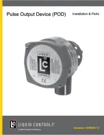
Pulse Output Device

9

Get the latest PDF manual:

https://www.lcmeter.com/resources/technical/manuals

Mobile/online version of this manual:

https://www.lcmeter.com/manuals

Specifications

Voltage

·

9 to 30 VDC

·

POD5 has a 5 VDC minimum but is not IECEx approved

Current Supply

maximum

·

50 mA

Output Signal

Resolution

·

100 pulses per channel per revolution, unscaled (see the 

Output

Signal Resolutions

 table in 

General Information

 )

Square Wave

·

Single channel output – Channel A or channel B

·

Quadrature channel output – Channel A and channel

Pulse Timing

·

Nominal 50% on and 50% off

Rise/Fall Time of

Pulse

·

< 5 µ s

Output

·

Current sinking 100 mA maximum in “ON” state

·

V+ supply @ 2.2 KΩ in “OFF” state.

·

Optional open-drain FET (Field-Effect Transistor).

·

FET rating (drain to source voltage) 30 VDC maximum

Pulse

Transmission

Distance

·

5,000 feet (1,524 meters)

Pulse Output

Fidelity

·

ISO 6551 Level A

·

API MPMS Chapter 5.5; Level A

·

OIML R117-1

·

Measurement Canada’s SVM-1

Materials of

Construction

·

Aluminum Alloy ADC12

·

Powder Coat: Corro-Coat PE 74-141 Polyester

Cable Entry

·

½"-14 NPT

6

Summary of Contents for POD1

Page 1: ......

Page 2: ...l Get the latest PDF manual Table of Contents Resources in this Guide 3 Publication Updates 3 Safety Procedures 4 General Information 6 Specifications 9 Dimensions 10 Regulatory Compliance Tag Marking...

Page 3: ...ards present when using the Liquid Controls Meter on LP gas and other products The reading of these warnings and the avoidance of such hazards is strictly in the hands of the owner operators of the eq...

Page 4: ...ess to appropriate fire extinguishers for your product Consult with your local fire department state and local codes to ensure adequate preparation Read this manual and all the literature provided in...

Page 5: ...tions in accordance with the requirements of the authority having jurisdiction Peripheral equipment must be suitable for the hazardous location where it is installed L quipement p riph rique doit tre...

Page 6: ...es the dynamic seal of the packing gland and isolates the electronics from the process fluid in the meter Inside the electronics compartment an optical shaft encoder converts the rotary motion into a...

Page 7: ...ing 100 PPR Quad Pulser 9 to 30VDC POD3 Blade Drive with Buna N O Ring 100 PPR Quad Pulser 9 to 30VDC POD4 Blade Drive with PTFE O Ring 100 PPR Quad Pulser 9 to 30VDC POD5 Fork Drive with Buna N O Rin...

Page 8: ...te K Factors and Volumetic Reference Data When initially calibrating a specific meter model the K Factor Pulses Unit values given below are for reference only and are not to be used as a final K Facto...

Page 9: ...quare Wave Single channel output Channel A or channel B Quadrature channel output Channel A and channel Pulse Timing Nominal 50 on and 50 off Rise Fall Time of Pulse 5 s Output Current sinking 100 mA...

Page 10: ...perature Range 40 to 176 F 40 to 80 C Humidity Range 0 100 non condensing Shock 50 G for 10 ms Vibration 1 G at 10 150 Hz Electromagnetic Compatibility EMI RFI etc POD with PC Board 84120 EU Directive...

Page 11: ...EX Directive with a certificate number Presafe 18 ATEX 12438X and in 2011 to IECEx scheme with a certificate number IECEx DNV 11 0012X where X represents the following Special Conditions for Safe Use...

Page 12: ...evaluated by UL for outdoor use to provide protection against water and dust and an increased level of protection against corrosion and that will be undamaged by the external formation of ice UL Liste...

Page 13: ...Pulse Output Device 13 Get the latest PDF manual https www lcmeter com resources technical manuals Mobile online version of this manual https www lcmeter com manuals Bill of Materials...

Page 14: ...Pulse Output Device 14 Get the latest PDF manual https www lcmeter com resources technical manuals Mobile online version of this manual https www lcmeter com manuals...

Page 15: ...rocedure Relieving Internal Pressure Procedure for LPG and NH3 Meters 1 Close the belly valve of the supply tank 2 Close the valve on the vapor return line 3 Close the manual valve in the supply line...

Page 16: ...ed However when using conduit the hub should face down so moisture that may accumulate in the conduit will drain away from the POD electronics 3 Remove the mechanical counter adjuster and adjuster dri...

Page 17: ...stallations section above There are two types of packing gland POD driver tangs blade type and fork type Blade type packing glands must be replaced with blade type PODs Fork type packing glands must b...

Page 18: ...re applications The POD Extension is used to extend the connection away from the meter There are four POD Extension models available 49754 POD1 or POD5 Fork Drive with Buna N O Ring 49756 POD2 Fork Dr...

Page 19: ...k type POD Extensions 2 Install the POD Extension using the two screws provided There are two sets of holes in the POD and the other is 1 apart Line up the holes with the meter to determine which set...

Page 20: ...o maintain the hazardous location ratings on the product Use Ex d certified cable glands only For ambient temperatures above 70 C use field wiring rated 20 C above the maximum ambient temperature WIRI...

Page 21: ...ward and reverse flow both channels which are in quadrature to each other must be used Channel A will lead Channel B by 90 in one flow direction and Channel B will lead Channel A in the reverse direct...

Page 22: ...leading Channel B For reverse flow applications counterclockwise Channel B leads Channel A NOTE Quadrature channel voltage output is 90 out of phase with Channel B POD Wiring Schematics Single Channel...

Page 23: ...www lcmeter com manuals Power Source Requirement An isolation source and overcurrent protective device rated 5A max must be installed in the power circuit If a 5A max isolation source and overcurrent...

Page 24: ......

Reviews: