background image

4

SAFETY PRECAUTIONS

General Safety Precautions


The installation of solar photovoltaic systems requires specialized skills and 
knowledge. The installer assumes all risk of injury, including risk of electric shock. 
Module installation should be performed only by qualified persons.


All modules come with a permanently attached junction box and 14 AWG PV 
cable terminated in PV connectors. Your dealer can provide additional extension 
cables to simplify module wiring.


Exercise caution when wiring or handling modules exposed to sunlight.


Do not connect or disconnect wires attached to photovoltaic modules when 
modules are exposed to sunlight, otherwise an electric arc may occur. Arcs 
can cause burns, fires or other safety problems. Always exercise caution when 
connecting and disconnecting wiring on modules.


Photovoltaic solar modules convert light energy to direct-current electrical 
energy and are designed for outdoor use. Proper design of support structures is 
the responsibility of the system designer and installer.


Modules may be ground mounted, pole mounted, or mounted on rooftops.


Do not attempt to disassemble the module, and do not remove any attached 
nameplates or components. Doing so will void the warranty.


Do not apply paint or adhesive to the module.


Do not use mirrors or other hardware to artificially concentrate sunlight on the 
module.


When installing modules, observe all applicable local, regional and national codes 
& regulations. Obtain a building and/or electrical permit when required.


These solar modules are not rated for grid-tied solar systems, they are meant 
solely for off-grid solar systems.

Work Safely


Wear protective eye wear and appropriate clothing during installation. Use 
extreme caution when working with electricity and when working around 
batteries. Use properly insulated tools only. 


Use care when working on an RV roof, always use rated safety harnesses and 
ladders during installation and maintenance. 

Summary of Contents for GS-M120-370-FAB1

Page 1: ...370W RIGID SOLAR PANEL MODEL GS M120 370 FAB1 USER MANUAL Product picture for reference only...

Page 2: ...on for safe use installation and maintenance of the product Please keep this instruction manual in a safe place for future reference This will ensure safe use and reduce the risk of injury Be sure to...

Page 3: ...lar Photovoltaic System 5 MECHANICAL INSTALLATION 5 General Installation Notes 5 Selecting the Mounting Location 5 Selecting the Proper Mounting Structure and Hardware 6 Mounting Methods 6 Secure the...

Page 4: ...ons must be read and understood before attempting installation If there are any questions please contact your dealer for further information The installer should conform to all safety precautions in t...

Page 5: ...rrent electrical energy and are designed for outdoor use Proper design of support structures is the responsibility of the system designer and installer Modules may be ground mounted pole mounted or mo...

Page 6: ...articular photovoltaic system Under normal operating conditions PV modules will produce currents and voltages that are different than those listed in the data sheet Data sheet values are applicable at...

Page 7: ...t be securely attached to the mounting structure using six mounting points for normal installation Load calculations are the responsibility of the system designer or installer The mounting structure a...

Page 8: ...ssive forces due to the thermal expansion of the support structures Secure the Solar Panel to the RV Roof 1 Mount the solar panel through the such that at least 4 of the mounting feet have screws pene...

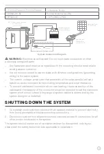
Page 9: ...wiring in the same system The current voltage and power characteristics of the solar panel s will vary based on environmental criteria including temperature and solar irradiance To prevent cables and...

Page 10: ...hey are clean secure undamaged and free of corrosion Remove snow ice or other debris when build up occurs Caution Observe the maintenance instructions for all components used in the system such as sup...

Page 11: ...smission rate and low iron tempered glass 1 8 3 2mm Back TPT Encapsulation material EVA Frame Black Anodized Aluminum Dimension W x H x D 407 8x 691 8 x 13 8 1038 x 1755 x 35mm Weight 40 2lbs 20 5kg C...

Page 12: ...een provided Any unauthorized use shall void any applicable warranty The information contained in this manual is subject to change without notice and at the sole discretion of Lippert Revised editions...

Reviews: