8
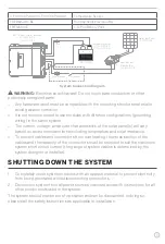
C-FSCC60PW-A01/C-FSCC60PW-A02
Temperature Sensor
FSEB30JWO-BL
Rooftop Solar Electrical Box
FBF12A100E
LiFePo4 Battery Pack
+
Disconnect
Fuse\Breaker
Fuse
Rooftop Solar
Electrical Box
FSEB30JWO-BL
+
-
-
Rigid Solar Panel
FSFP37MW-BL
Battery
+
-
Temperature Sensor
C-FSCC60PW-A01
C-FSCC60PW-A02
FBF12A100E
MPPT Solar Charge Controller
FSCC30PW-BL
FSCC60PW-BL
System Connection Diagram
Optional
WARNING:
Electrical shock hazard! Do not touch bare conductors or other
potentially energized parts.
–
Any hardware used must be compatible with the mounting structure material to
avoid galvanic corrosion.
–
It is not recommended to use modules with different configurations (grounding,
wiring) in the same system.
–
The current, voltage, and power characteristics of the solar panel(s) will vary
based on environmental criteria including temperature and solar irradiance.
–
To prevent cables and connectors from overheating, the cross section of the
cables and the capacity of the connectors must be selected to suit the maximum
system short circuit current (the gauge of system cables is determined by the
system designer or installer.).
SHUTTING DOWN THE SYSTEM
1. Completely cover system modules with an opaque material to prevent electricity
from being generated while disconnecting connectors.
2. Disconnect system from all power sources in accordance with instructions for all
other components used in the system.
The system should now be out of operation and can be dismantled. In doing so,
observe all the safety instructions as applicable to installation.


