


15
Chapter 5: Configuring the Gateway
How to Access the Web-based Utility
ADSL2 Gateway with 4-Port Switch
How to Access the Web-based Utility
To access the web-based utility, launch Internet Explorer or Netscape Navigator, and enter the Gateway’s default
IP address, 192.168.1.1, in the Address field. Then press Enter.
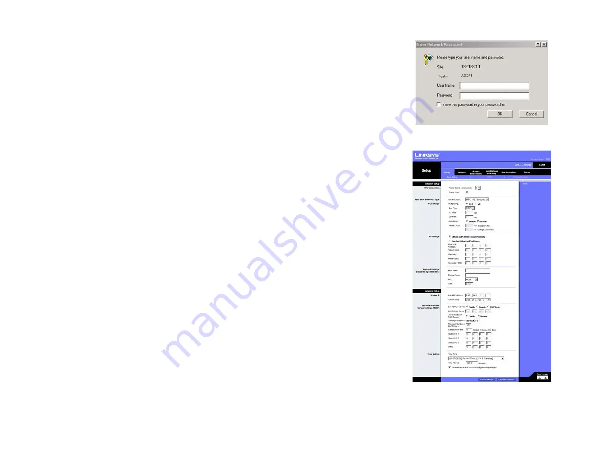
A password request page, shown in Figure 5-1 will appear. (non-Windows XP users will see a similar screen.)
Enter
admin
(the default user name) in the User Name field, and enter
admin
(the default password) in the
Password field. Then click the
OK
button.
The Setup Tab
The Basic Setup Tab
The first screen that appears is the Basic Setup tab. This tab allows you to change the Gateway's general
settings. Change these settings as described here and click the
Save Settings
button to save your changes or
Cancel Changes
to cancel your changes.
Internet Setup
•
PVC Connection. Select a PVC connection number from the drop-down menu. Then, select the
Enable Now
to
enable the connection.
•
VC Settings. Virtual Circuits (VPI and VCI): These fields consist of two items: VPI (Virtual Path Identifier) and VCI
(Virtual Channel Identifier). Your ISP will provide the correct settings for these fields.
•
Multiplexing: Select
LLC
or
VC
, depending on your ISP.
•
QOS Type: Select from the drop-down menu:
CBR
, Continuous Bit Rate to specify fixed bandwidth for
voice or data traffic;
UBR
, Unspecific Bit Rate for application that are none-time sensitive, such as email;
or
VBR
, Variable Bite Rate for Bursty traffic and bandwidth sharing with other application.
•
Pcr Rate: Peak Cell Rate, divide the DSL line rate by 424 to find the PCR to get the maximum rate the
sender can send cells. Enter the rate in the field (if required by your service provider).
•
Scr Rate: Sustain Cell Rate, sets the average cell rate that can be transmitted. SCR normally less than
PCR. Enter the rate in the field (if required by your service provider).
•
Autodetect: Select
Enable
to have the settings automatically entered or
Disable
to enter the values
manually.
•
Virtual Circuit: Enter the VPI and VCi ranges in the fields.
Figure 5-2: Basic Setup Tab
Figure 5-1: Password Screen


