Linkam Scientific Instruments LinkPad T96 User Manual Download Page 13

© 2017 Linkam Scientific Instruments Ltd.

13

v1.1.0

The only changes that can be made are to switch the displayed units between Bar, MPa and Torr. This cannot be changed while a profile is active.

Note: 

Linkam recommends the use of a pressure gauge with these stage types. If you do not have one please contact Linkam Scientific or your local

distributor.

Motorised XY stages

This section applied to stages with motorised XY movement, such as the MDS600.

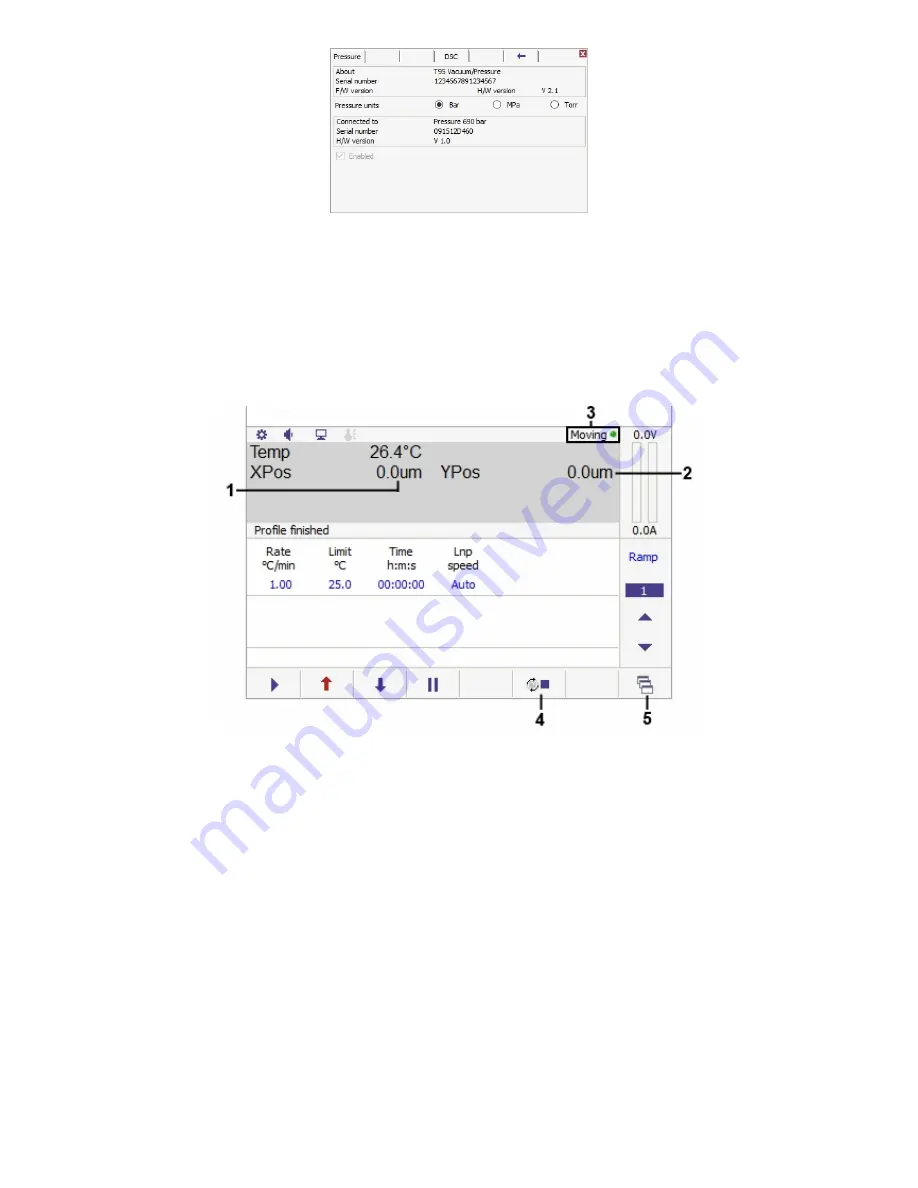
Additional main screen display items:

When a motorised stage is connected, the main control screen will display the following additional information:

1.

X axis position

2.

Y axis position

3.

MDS motor indicator

4.

Stop motion control

5.

Manual motor control

The X and Y position values (1) and (2) are the distance in µm from the zero position (which can be set at any physical location). Positive values
indicate a position above/right of the zero point, whereas negative values indicate a position below/left of the zero point.
The indicator light (3) will be green while the motors are at rest and will switch to red when the motors are in motion.
Tap the stop motion control (4) to stop motor movement at any time.  Heating will not be stopped when this control is used.

Summary of Contents for LinkPad T96

Page 1: ...T96 LinkPad User Guide Linkam Scientific Instruments USER GUIDE 1 1 0 ...

Page 2: ...This page is intentionally blank ...

Page 3: ...asic stage controls 9 Profiles and Ramps 9 Creating a profile 10 Running The Profile 11 Stage Specific Controls 11 Vacuum stages 12 Pressure stages 13 Motorised XY stages 15 Tensile stages 18 DSC stages 19 Humidity control 21 Options and Information 21 Connected hardware 22 Option board Information 23 Sample Calibration 25 Troubleshooting 25 Control and connection Errors ...

Page 4: ... 2017 Linkam Scientific Instruments Ltd 4 v1 1 0 Introduction Welcome to your LinkPad Manual This guide will explain the use ofthe optional LinkPad Controller ...

Page 5: ... be used in conjunction with a Linkam T96 temperature controller Please refer to the T96 Controller manual before use Warranty This equipment has a warranty against defects in material and workmanship for a period of12 months from the date ofshipping Linkam will either repair or replace products that prove to be defective For warranty service or repair this product must be returned to Linkam or a ...

Page 6: ...basic functions ofyour Linkam stage The display screen is touch sensitive so you can simply operate the Linkpad by finger touches Ifyou are using the LinkPad concurrently with the optional LINK software and a PC connection only sensor data such as temperature will be shown The power indicators still operate as does the Setup button ...

Page 7: ...old time 5 Liquid nitrogen pump speed only present ifan LNP96 is connected to the T96 6 Start control 7 Heat override control 8 Cool override control 9 Pause control 10 Ramp number display Ramp options 11 Next ramp control 12 Previous ramp control 13 Settings and Information 14 Volume icon 15 Computer control icon 16 Sample Calibration icon 17 Stage power input display 18 Feature control functions...

Page 8: ...means that the system will control the flow rate ofliquid nitrogen to match the rate oftemperature change specified Ifyou wish to manually control the speed ofthe liquid nitrogen flow tap on the LNP speed 5 and a keypad will appear Tap on Man to change the pump to manual mode and enter the desired pump speed as a percentage ofmaximum speed with 100 being maximum speed Note That using the LNP in th...

Page 9: ...et end ramp 7 Toggle cycle mode The copy ramp control 1 will copy all the values in the currently selected ramp into memory these values can be then pasted into another ramp via the paste ramp control 2 The clear profile control 3 will reset all ramps to default values and the clear ramp control 4 will reset the currently selected ramp to zero values The clear ramp control cannot be used on ramp 1...

Page 10: ... simply touching on any ofthe displayed values 2 3 4 5 and entering a new value Pause heating cooling or the hold time Touching the pause button 9 during the profile will stop the heating cooling until either the heat 7 or cool 8 button is pressed or the limit is changed Ifthe limit has been reached touching the pause will stop the time countdown Touching the pause or changing the hold time will b...

Page 11: ...acuum level control 3 MV196 motorised valve operation To set the vacuum level tap on the vacuum control 2 and enter the required value Mororised valve statusindicators These indicators show at a glance the status ofthe valve The Max indicator 1 will be illuminated blue when the vacuum level is at maximum i e this light will be illuminated when the valve is in its fully closed position The Atmos in...

Page 12: ...en mBar mTorr and kPa This cannot be changed while a profile is active Systems shipped with a MV196 motorised vacuum valve will also be fitted with a motor control expansion board No changes can be made on this screen it is for information only Pressure stages This section applies to all stages that can be pressurised to above atmospheric pressure Including THMS600PS and CCR1000 The only additiona...

Page 13: ...ed stage is connected the main control screen will display the following additional information 1 X axis position 2 Yaxis position 3 MDS motor indicator 4 Stop motion control 5 Manual motor control The X and Yposition values 1 and 2 are the distance in µm from the zero position which can be set at any physical location Positive values indicate a position above right ofthe zero point whereas negati...

Page 14: ...ue value and entering the required velocity on the resulting keypad The go to zero control 4 will move the sample carrier to the currently set zero position The set zero control 5 will set the current position ofthe sample carrier as the zero point This will change the XPos and YPos values on the main screen to zero without physically moving the sample carrier Note Ifusing a camera see the section...

Page 15: ...ensile Setup 6 Current jaw status indicators 7 Tensile pause button Current jaw status 6 shows the current motion status ofthe jaws Ifthey are currently in motion the moving indicator will be red and green when they are stationary The open and closed indicators will light up blue when the jaws are in their fully open and closed positions respectively Atensile motion pause button 7 will appear when...

Page 16: ...ion and tap the start action button 9 to perform the action the Zero force 2 and distance 3 controls allow you to set the force and distance readings to zero prior to starting the action The movement ofthe tension jaws will be shown on the graphical representation 1 Tensile Setup Use this screen to set calibration values for your TSTsystem 1 Proportional force 2 Integral force 3 Derivative force 4...

Page 17: ...hereas the true strain is similar but based on the instantaneous length ofthe specimen as the test progresses Choose between true and engineering strain using the strain radio buttons 2 Tick the box ifyou wish to show the strain in percent The Show calibrated values check box 3 switches the display between the raw output from the transducer and the calibrated value The default is to display the ca...

Page 18: ...atic the tensile displays will change to Cal versions while this is happening as below While these readings show DCal and FCal do not operate the stage the readings will revert to normal once the calibration is complete and the system is ready for use Important note The Force calibration button is only for use by Linkam Scientific and requires a password to access Do not attempt to use this contro...

Page 19: ... software Expansion board setup DSC600 DSCX600 and DSC450 stages will have a DSC sensor expansion board fitted to their T96 controller which has the following setup screen accessed by taping on the options bar and taping on the blue arrow No changes can be made on this screen it is for information only Humidity control This section applies ifyou have a Linkam RH95 humidity controller attached to y...

Page 20: ... display 1 will update to show which desiccant tube is currently drying out by highlighting it in red and a blue arrow will appear next to the currently active tube The water temperature display 2 shows the temperature ofthe water bottle in the RH95 The humidity supply tube has a heater wire inside it to maintain the air temperature The power display 3 shows the power being put into this heater wi...

Page 21: ...uttons 1 The number ofdecimal places displayed on the temperature readout can be selected using the radio buttons 2 Either one two or three decimal places can be used For high temperature TSXXXX stages this changes from 0 decimal places to 1 decimal place Enabling the Enable signal o ps checkbox 3 brings up a representation ofthe green and pink rear panel 3 5mm connectors on the main running displ...

Page 22: ...96 System Controllers connected to a high temperature stage require a dual thermocouple option board This tab shows which stage is connected and it s serial number The other input ofthe dual card will be blank Tensile Tab T96 System Controllers setup for a tensile stage require a signal conditioning option board This tab shows which beam type is connected to the system allows the user to select wh...

Page 23: ...rds hardware Sample Calibration Depending on the specific properties ofyour sample for example total mass thermal conductivity surface area and flatness it is possible that thermal losses between the heating block and the sample or a temperature gradient through the sample may cause a difference between the reported temperature ofthe stage and the actual temperature ofyour sample To account for th...

Page 24: ...t different temperature ranges Ifyou do not wish to use a calibration point then leave both values the same The calibration points must be in ascending order oftemperature The temperature ranges chosen must not overlap The maximum offset within any point pair is 20 C Ifyou are experiencing a discrepancy ofgreater than 20 C please contact Linkam technical support Once the required values have been ...

Page 25: ...stage type connected requires an additional cable connected to an expansion board in the T96 but it is disconnected Power the unit offand check that any additional cables such as vacuum sensor or DSC sensor cable are connected and that you are using the correct stage lead for your stage This error occurs when the connected stage calls for option boards to be fitted into the T96 but the system cann...

Page 26: ...hen there is a fault with an accessory such as a vacuum gauge that is connected to an expansion board on the T96 controller If you see this message contact Linkam Scientific technical support This error occurs when there is an internal problem with a connected LNP96 Ifyou see this error please contact Linkam Scientific technical support This error occurs when the T96 controller does not recognise ...

Page 27: ...Linkam Scientific Instruments Ltd Tel 44 0 1737 363 476 Fax 44 0 1737 363 480 Email support linkam co uk Unit 8 Epsom Downs Metro Centre Waterfield Tadworth Surrey KT20 5LR UK www linkam co uk ...

Reviews: