background image

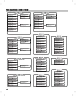
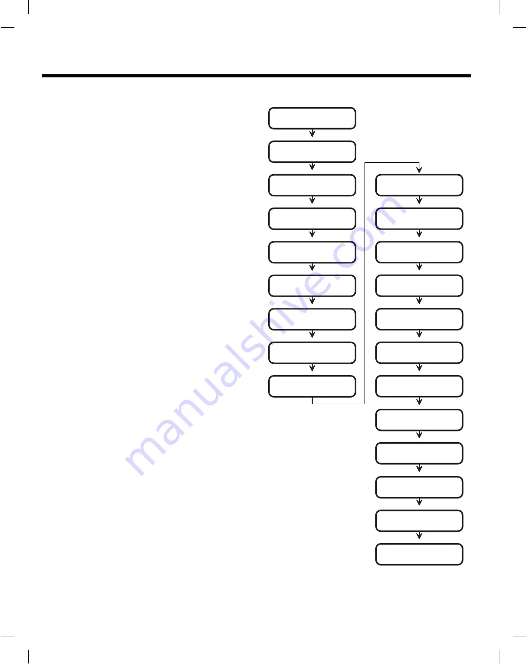
PROGRAMMING OUTLINE

The following outline is intended to guide you through the
programming of an AM/II system. The AM/II is programmed by
setting options in various program “Areas”. Use this outline in
conjunction with the following program area detail pages to set
up the system.

1.

Install and connect the AM/II as previously described.

2.

Fill out the Programming Worksheet (P/N 211677).

3.

Enter program mode (Hold the * key for 5 seconds or press
Esc on programming computer).

4.

Set date and time (standard time) in Time and Calendar
Area 20.

5.

If the system is going to be networked, Area 22 Network
Address must be set. (If AccessBase is used, this is the only
local programing step needed.)

6.

Determine the button configurations and enter them in Button
Schedule Area 11.

7.

Program any time zones in Time Zone Area 13.

8.

Program the door access in Door Schedules Area 12.

9.

Program the validation groups in Validation Group Area 10.

10.

Set all additional system options in the System Setup Area 22.

11.

Program all single transmitters using Single Transmitters
Area 01.

12.

Program all block coded transmitters using Block Area 02.

13.

Program all MGT safety edge obstacle transmitters using
Obstacle Transmitter Area 03.

14.

Program all “MagicWand” transmitters using Magic Wand Xmtr
Area 04.

15.

Program all keypad entry codes using Entry Code Area 05.

16.

Program all block card codes using Block Card Codes Area 06.

17.

Program the relay output options using Relay Setup Area 21.

18.

Program the facility and site codes (if used) using Facility/Site
Codes Area 23.

19.

Set any remote accessory device address and options using
Configure Remote Devices Area 25.

20.

If using the Model AE-1 or AE-2 telephone entry module,
program the telephone entry settings using Telephone Entry
Setup Area 27.

21.

If using the Model AE-1 or AE-2 telephone entry module,
program the telephone and directory numbers and names
using Telephone Entry Numbers Area 07.

22.

Setup the ACCESS OUT terminals if connecting to an external
access control panel using the Configure Access Out Area 26.

23.

Examine the system, single transmitter, block transmitter, entry
code and block card reports for a system programming
overview. Use the System Reports/Utilities Area 30 to view
(using a terminal, computer or printer) the reports.

24.

Test the system and adjust the red RADIO RANGE knob to
determine the optimum range of the receiver.

SETUP DATE AND TIME

(AREA 20)

SET NETWORK ADDRESS

(AREA 22)

SET BUTTON SCHEDULE

(AREA 11)

SET TIME ZONES

(AREA 13)

SET DOOR SCHEDULES

(AREA 12)

SET VALIDATION GROUPS

(AREA 10)

SET ALL SYSTEM OPTIONS

(AREA 22)

PROGRAM SINGLE

TRANSMITTERS

(AREA 01)

PROGRAM BLOCK CODED

TRANSMITTERS

(AREA 02)

PROGRAM OBSTACLE

TRANSMITTERS

(AREA 03)

PROGRAM MAGIC WAND

TRANSMITTERS

(AREA 04)

PROGRAM KEYPAD

ENTRY CODES

(AREA 05)

PROGRAM BLOCK

CARD CODES

(AREA 06)

SET RELAY OPTIONS

(AREA 21)

SET FACILITY AND SITE CODES

(AREA 23)

CONFIGURE REMOTE DEVICES

(AREA 25)

CONFIGURE ACCESS OUT

(AREA 26)

PRINT OR VIEW

SYSTEM REPORTS

(AREA 30)

TEST SYSTEM

SETUP TELEPHONE ENTRY

(AREA 27)

PROGRAM TELEPHONE ENTRY

NUMBERS AND NAMES

(AREA 07)

40

Summary of Contents for AM/II

Page 1: ...S D SYSTEM POWER RESET DISPLAY CONTRAST B O 1 O 1 O 1 B O 1 N O COM N C N O COM N C N O COM N C N O COM N C EARTH GROUND ACCESS OUT KEYPAD IN CHANNEL A CHANNEL B CHANNEL C CHANNEL D READER IN 14 24 VA...

Page 2: ...dem Connections 31 ACCESS OUT CONNECTIONS 32 NETWORK CONNECTIONS 33 SYSTEM POWER UP 34 First Time Power up 34 Internal Diagnostic Checks 34 Watchdog Monitor 34 MEDIA ENCODING 34 Transmitter Coding 34...

Page 3: ...Setting Network Address 54 Setting Keypad Strike Outs 54 Setting Door Ajar Time 54 Setting Local Password 54 Setting Remote Password 54 Setting Priority Access Password 54 AREA 23 Facility Site Codes...

Page 4: ...rol systems The AM II can act as a wireless receiver for an existing access control system When interconnected to a Sentex Infinity system the AM II can simulate two Sentex card readers receiving sign...

Page 5: ...periods each Time zone access validation 15 time zones with 4 periods each Day of week and holiday access validation up to 24 expiring holidays and 24 non expiring holidays Door access restriction for...

Page 6: ...ACCESSORY DEVICES 5 B u t t o n M e g a C o d e T r a n s m i t t e r C a n c o n t r o l a l l r e l a y c h a n n e l s o r b e u s e d a s a m a g i c w a n d t r a n s m i t t e r M D T 4 M D T 1...

Page 7: ...n by pressing an ACCESS button 16 EXTERNAL CONTROL INDICATORS MAGIC WAND indicator lights when the special MAGIC WAND transmitter is activated by a system administrator OBSTACLE indicator lights when...

Page 8: ...INALS DOOR SENSE OPEN REQ RELAY TERMINALS USER S TRANSMITTERS OBSTACLE TRANSMITTERS ANOTHER AM II ANOTHER AM II UP TO 8 NETWORK UNITS EXTERNAL ACCESS CONTROL PANEL AM KP KEYPAD DV4 AM KP KEYPAD DV5 AM...

Page 9: ...A 2000 directional antenna is used to receive signals from the user s transmitters The radio gain control knob can be used to custom tailor the reception area to the installation ACCESS DEVICES The ac...

Page 10: ...BUTTON TOP BUTTON LEFT BUTTON RIGHT BUTTON BOTTOM RIGHT BUTTON BOTTOM LEFT BUTTON LEFT BUTTON LEFT BUTTON RIGHT BUTTON ANY TRANSMITTER BUTTON CAN BE PROGRAMMED TO ACTIVATE ANY RELAY CHANNEL SPECIAL I...

Page 11: ...groups Door schedule 0 DS0 always allows access to all four door relay channels Up to 15 door schedules can be programmed UP TO 15 DIFFERENT DOOR SCHEDULES DS1 DS15 CAN BE SET RELAY CHANNEL A RELAY CH...

Page 12: ...lows 24 hour access VALID DAYS SET WHICH DAY S THE TIME ZONE IS ACTIVE HOLIDAY OPTION ALLOWS ACCESS ON PROGRAMMED HOLIDAY DAYS UP TO 15 DIFFERENT TIME ZONES TZ1 TZ15 CAN BE SET UP TO FOUR SEPARATE TIM...

Page 13: ...t be set to IN for anti passback to function Keypad strikeout can be set from one to seven failed attempts 5 6 7 8 9 0 1 2 3 4 5 6 7 8 9 0 1 2 3 4 YELLOW LIGHT SHOWS LOCKED OUT CONDITION WHEN ANTI PAS...

Page 14: ...and anti passback timer before programming validation groups Up to 15 validation groups can be programmed Each selects a door schedule time zone button schedule and anti passback option Validation gr...

Page 15: ...PRINTOUT Event Log Report Jun 22 1995 09 56 39 Page 001 Installation South Hills Apartments AM II Unit 1 08 55 35 06 22 95 0 0 sTx 00003 B Unit 1 08 51 21 06 22 95 0 2 Crd 01470 B Front Door Card Read...

Page 16: ...ARD CODES FROM ONE OR TWO CARD SWIPE READERS MODEL AM RPR RADIO PROXIMITY RECEIVER ACCEPTS ID CODES FROM TRANSMITTERS AS USERS ACTIVATE THEM NEXT TO RECEIVER MODEL AM RRR REMOTE RADIO RECEIVER ACCEPTS...

Page 17: ...S M I T T E R S S E Q U E N T A L L Y C O D E D A T T H E F A C T O R Y A N D P R O G R A M M E D B Y E N T E R I N G T H E S T A R T I N G A N D E N D I N G B L O C K N U M B E R S B L O C K C O D E...

Page 18: ...ON PULSE TOGGLE AND LATCH OUTPUTS SENSING INPUTS OPEN REQUEST INPUT AVAILABLE FOR RELAY CHANNELS A B NORMALLY OPEN SWITCH DOOR SENSE INPUT AVAILABLE FOR RELAY CHANNELS A B NORMALLY CLOSED SWITCH B REL...

Page 19: ...S P L A Y S S Y S T E M R E P O R T S L O C A L L Y P R O G R A M A M I I S T O R E A M I I M E M O R Y T O D I S K L O A D A M I I M E M O R Y F R O M D I S K U S E M O D E L A 2 C C A B L E COMPUTER...

Page 20: ...ST SYSTEM EXPANSION MEMORY CARD RADIO DECODE ACCESS GRANTED READER KEYPAD ACCESS OUT DATA ACCESS IN DATA ACCESS A ACCESS B ACCESS C OBSTACLE MAGIC WAND ACCESS D B O 1 O 1 O 1 B O 1 N O COM N C N O COM...

Page 21: ...R MODEL A2M CABLE MODEL A2C CABLE MEMORY EXPANSION CARD MEDIUM 64 K SMALL 16 K LARGE 128 K X LARGE 256 K WARNING TURN THE POWER SWITCH OFF BEFORE INSTALLING OR REMOVING THIS MEMORY EXPANSION CARD SEVE...

Page 22: ...ing an installation diagram 3 Mount the AM II in an optional cabinet if required 4 Connect the antenna 5 Install any remote accessory devices 6 Wire connections to the AM II terminals A Install a grou...

Page 23: ...ontrol panel Mounting Screws Used to mount the AM II inside the cabinet Installing the Memory Module Four sizes of memory modules are available for the AM II SMALL 16K MEMORY MEDIUM 64K MEMORY LARGE 1...

Page 24: ...N C N O COM N C N O COM N C EARTH GROUND ACCESS OUT KEYPAD IN CHANNEL A CHANNEL B CHANNEL C CHANNEL D READER IN 14 24 VAC 12 35 VDC AC POWER INPUT DC POWER INPUT NETWORK OK WARNING SEVERE ELECTRICAL D...

Page 25: ...ower requirements of the AM II and it s complement of devices WARNING Never short the terminals of the transformer together This will cause the internal fuse to blow The transformer must be connected...

Page 26: ...feet use WEICO 9405 20 AWG Load Number Each hardwired remote accessory device has been assigned a load number Homerun wiring is recommended for accessories although multiple accessories can be wired o...

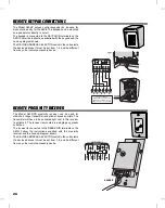
Page 27: ...ntenna or with the EXA 1000 or EXA 2000 remote antennas The receiver is connected to the READER IN terminals on the AM II Follow the instructions supplied with the remote receiver and the hook up diag...

Page 28: ...a short range transmitter reception at access portals The transmitter will have to be activated right next to this receiver to activate it The receiver is mounted in a single gang plastic outlet box T...

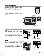
Page 29: ...access portal from inside the controlled area Door Sense The door sense terminals for relays A B are used with normally closed door contacts The contacts monitor the position of the access door When...

Page 30: ...nted by the AM II the alarm would be triggered When programmed for shunt operation relay channel C will mirror the activation of relay channel A Relay channel D will mirror the activation of relay cha...

Page 31: ...nection is made to a directory party they can press the 5 digit on their telephone to activate the CCTV relay A CCTV camera would activate to send a picture of the entry area to the directory party N...

Page 32: ...DATA ACCESS A ACCESS B ACCESS C OBSTACLE MAGIC WAND ACCESS D B O 1 O 1 O 1 B O 1 N O COM N C N O COM N C N O COM N C N O COM N C EARTH GROUND ACCESS OUT KEYPAD IN CHANNEL A CHANNEL B CHANNEL C CHANNEL...

Page 33: ...ote programming of the AM II The AM II can connect to most personal computer external modems Use the Model A2M cable to connect the AM II to a modem Connection to a modem allows you to call the AM II...

Page 34: ...R 1 B RDR 0 5 VDC GND SENTEX INFINITY SYSTEM 3 CONDUCTOR SHIELDED CABLE OPTIONAL 2 DEVICE HOOKUP USE BELDEN TYPE 9925 CABLE OR EQUIVALENT MAXIMUM WIRE RUN DISTANCE 500 FEET RADIO DECODE ACCESS GRANTED...

Page 35: ...ACCESS D B O 1 O 1 O 1 B O 1 N O COM N C N O COM N C N O COM N C N O COM N C EARTH GROUND ACCESS OUT KEYPAD IN CHANNEL A CHANNEL B CHANNEL C CHANNEL D READER IN 14 24VAC 12 35 VDC ACPOWER INPUT DC PO...

Page 36: ...the AM II will remember all of the media code data Transmitter Coding There is no programming of transmitter codes or setting of dipswitches required to set up the system Each transmitter is preset a...

Page 37: ...code Radio Indicator The RADIO indicator displays the output of the built in radio receiver The visual display is used to determine when signals are on the air on the frequency that the radio is tune...

Page 38: ...g step Pressing and holding the key for about three seconds in Program Mode will cause the AM II to exit Program Mode and return to the normal Run Mode While in Run Mode pressing and holding the key a...

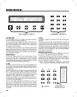
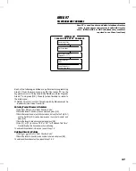
Page 39: ...NOTE The system will automatically exit Program Mode after five minutes of programming inactivity U P D O W N A R R O W S W I L L M O V E B E T W E E N M E N U T O P I C S O K K E Y S E L E C T S S U...

Page 40: ...0000 Delete One Single Xmtr Transmitter ID 0000 Status of Single Xmtr Transmitter ID 0000 1 7 1 5A Item Code Press OK When Ready 1 6 Enter Expiration Date Expires On mm dd yyyy AREA 03 OBSTACLE TRANS...

Page 41: ...Time Zone 2 0 1 2 3 4 5 6 7 8 9 10 11 12 13 14 15 Assign Time Zone 3 0 1 2 3 4 5 6 7 8 9 10 11 12 13 14 15 Assign Time Zone 4 0 1 2 3 4 5 6 7 8 9 10 11 12 13 14 15 SYSTEM SETUP AREA 22 22 1 22 2 Insta...

Page 42: ...ptions using Relay Setup Area 21 18 Program the facility and site codes if used using Facility Site Codes Area 23 19 Set any remote accessory device address and options using Configure Remote Devices...

Page 43: ...gle Transmitters Use or to scroll to Enter Single Xmtr Numb Enter the transmitter ID to reactivate and press OK Use or to select Reactivate Single Xmtr and press OK To reactivate additional transmitte...

Page 44: ...To suspend any additional transmitters repeat Steps 1 3 Reactivating Block Transmitters Use or to scroll to Enter Transmitter Numb Enter the transmitter ID to reactivate and press OK Use or to select...

Page 45: ...oll to Which Obstacle Xmtr Use or to select OBTx1 or OBTx2 obstacle transmitter 1 for Channel C obstacle transmitter 2 for Channel D Press OK when desired selection is blinking Use or to scroll to Lea...

Page 46: ...Which MagicWand Xmtr Use the and keys to choose MW1 MW2 MW3 MW4 MW5 MW6 MW7 MW8 for Magic Wand transmitter 1 8 Press OK when desired selection is blinking Use or to scroll to Learn MagicWand Xmtr and...

Page 47: ...y Codes Use or to scroll to Suspend Entry Code Enter the entry code to suspend and press OK To suspend additional entry codes repeat Steps 1 2 Reactivating Entry Codes Use or to scroll to Reactivate E...

Page 48: ...K To suspend any additional block cards repeat Steps 1 3 Reactivating Block Card Codes Use or to scroll to Enter Card Number Enter the card number to reactivate and press OK Use or to select Reactivat...

Page 49: ...ory Code Enter the tenant s directory code number and press OK Enter the tenant s name up to 24 characters but only the first 16 AE 1 and the first 20 AE 2 can be displayed on the current models and p...

Page 50: ...program and press OK Unit displays Door Schedule 0 15 Enter 0 7 to select a door schedule for the validation group selected and press OK Door schedule 0 allows access to all four relay channels Unit d...

Page 51: ...Setting the Channel B Button Schedule Use or to scroll to Channel B Valid Buttons Use or to choose which transmitter button s will activate relay channel B Press OK when the desired selection is blink...

Page 52: ...inished to return to the main menu Setting the Door Schedules Use or to scroll to Which Door Sch 1 15 Enter 1 15 and press OK Each door schedule has selectors for relay channels A B C D 0 NO door sche...

Page 53: ...nter the starting and ending times 24 hour format 1pm 13 00 for this time period The time zone selectedwillhaveaccessbetweenthetimeperiodsentered Press OK Unit displays Period 2 Begin End Time Enter t...

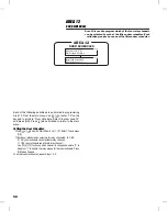
Page 54: ...Daylight Savings Use or to select Yes or No for daylight savings time adjustment When the desired response is blinking press OK Setting Keypad Downlight Time Use or to scroll to Downlight On Off time...

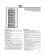
Page 55: ...blinking Unit displays Select Operation Use or to select Control Shunt Alarm Obstacle CCTV for the relay Press OK when desired selection is blinking NOTE Relays A B can only be programmed as control...

Page 56: ...es network activation After reset the network LED will be blinking Setting Keypad Strike Outs Use or to scroll to Keypad Strikes and Out Enter the number of keypad attempts allowed 1 7 before keypad l...

Page 57: ...cility code and press OK The transmitter facility code for the block of transmitters is labeled on the transmitter master carton The custom facility code number is determined by Linear at the time of...

Page 58: ...ning a terminal program Choose PC if the port is connected to a PC to receive raw standard transaction string data for further processing Changing Modem Initialization Strings Modem initialization str...

Page 59: ...is installed Unit displays Assign Control Channel Use or to select relay channel A D that the device will activate Press OK when desired selection is blinking Unit displays Access Direction Select Non...

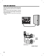
Page 60: ...sent from the ACCESS OUT terminals when any valid transmitter is decoded regardless if access is granted by the AM II The data sent is the Access Out Facility Code and the transmitter sequence number...

Page 61: ...when the desired selection is blinking Setting Talk Time Use or to scroll to Set Talk Time Enter the length of talk time allowed up to 255 seconds default is 60 seconds Press OK Editing Display Messag...

Page 62: ...the Model AM MOD modem for remote telephone connection Use or to scroll to Receive Memory Module Use or to select Yes Press OK Unit displays Begin File Transfer You have one minute to begin sending t...

Page 63: ...ock Xmtr Report Use or to select Yes Press OK Printing Entry Code Report Use or to scroll to Print Entry Code Report Use or to select Yes Press OK Printing Block Card Report Use or to scroll to Print...

Page 64: ...ic Wand transmitter the device can be disabled remotely without having to disconnect the operator from the AM II When service is being performed on a door with a door strike maintenance personnel migh...

Page 65: ...r controlling radio range OPEN REQUEST Contact closure to ground activates corresponding output relay DOOR SENSE Normally closed input to sense door status KEYPAD Integral 17 key silicone rubber keypa...

Page 66: ...Time 54 Door Schedules 9 50 Door Sense 27 E Earth Ground 23 Earth Ground Terminal 5 Editing Display Messages 59 Entering Block Card Codes 46 Block Transmitters 42 Entry Codes 45 Tenant Names Numbers...

Page 67: ...26 Remote Radio Receiver 25 Reset Button 5 RS 232 Jack 5 RS 232 Port 17 30 RS 232 Port Setup 56 S Sending Memory Module 60 Sensing Inputs 16 Sequence Number 35 Serial Port 31 Setting Anti passback Ti...

Page 68: ...l other warranties express or implied All products returned for warranty service require a Return Product Authorization Number RPA Contact Linear Technical Services at 1 800 421 1587 for an RPA and ot...

Reviews: