background image

LINDY ELECTRONICS LTD 

Installation & Use – English Guide 

Page 23


For example, consider a situation where two LINDY CPU Switch units are connected together (as 

shown in figures 7 and 8). To connect to the computer attached to port 3 on LINDY CPU Switch B 

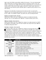
the user would hold down the hotkey keys then press 

 followed by 

, whilst keeping the hotkey 

keys pressed. This will have the effect of connecting to port ‘3’ of the LINDY CPU Switch which is 

connected into port ‘2’ of the first LINDY CPU Switch unit A. (Note: if you are cascading 16 port 

models then you will need to type a leading 0 before all single digit port numbers). 


For example to connect to port 3 on the LINDY CPU Switch cascaded off port 2 of your first LINDY 

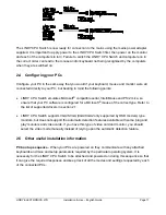
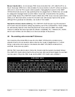
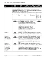
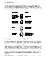
CPU Switch use:


 press 

ts

 release 


 press 

 release 

ts


For example to connect to port 14 on the LINDY CPU 16 OSD Switch cascaded off port 1 of your 

first LINDY CPU 16 OSD Switch use:


 press 

ts

 release 

 press 

 release 


 press 

 release 


 press 

 release 

ts


Summary of Contents for CPU 16 OSD Switch

Page 1: ...user serviceable parts within power adapter do not dismantle Plug the power adapter into a socket outlet close to the LINDY CPU Switch Do not use power adapter if power adapter case becomes damaged c...

Page 2: ...hich the receiver is connected d Consult the supplier or an experienced radio TV technician for help FCC Compliance Statement United States This equipment generates uses and can radiate radio frequenc...

Page 3: ...troller 16 3 4 Status display 17 3 5 Using the dual control ports A and B 17 3 6 Keyboard hotkey control 18 3 7 On screen menu control 20 3 8 Mouse control 22 3 9 RS232 control 22 3 10 LINDY CPU Switc...

Page 4: ...tores keyboard and mouse states when channel changed Yes Yes Yes Yes Yes Can be controlled remotely via an RS232 serial port No Yes Yes Yes Yes Supports high bandwidth monitors at resolutions up to 16...

Page 5: ...LINDY ELECTRONICS LTD Installation Use English Guide Page 5 1 3 Product information Figure 1 LINDY CPU Switch 2 port version supporting 2 PCs Figure 2 LINDY CPU Switch 4 port version supporting 4 PCs...

Page 6: ...Page 6 Installation Use English Guide LINDY ELECTRONICS LTD Figure 3 LINDY CPU 4 OSD Switch Front Rear views 4 port version supporting 4 PCs...

Page 7: ...ation Use English Guide Page 7 Figure 4 LINDY CPU 8 OSD Switch Front Rear views 8 port version supporting 8 PCs Figure 5 Remote control pad display Optional accessory not for use with the LINDY CPU 2...

Page 8: ...Page 8 Installation Use English Guide LINDY ELECTRONICS LTD Figure 6 LINDY CPU 16 OSD Switch Front Rear views 16 port version supporting 16 PCs...

Page 9: ...ree button mouse or an IntelliMouse The LINDY CPU Switch supports Internet Mice that are compatible with the Microsoft IntelliMouse These are fitted with a wheel or other scroll control and sometimes...

Page 10: ...that the power is disconnected from the LINDY CPU Switch and all devices which are to be attached LINDY CPU 2 4 Switches LINDY CPU 4 OSD 8 OSD 16 OSD Switches Connect the shared keyboard PS 2 mouse a...

Page 11: ...2 mice so ensure that your PC software is configured for a Microsoft mouse of the correct type Refer to the list of supported drivers in section 2 1 LINDY CPU Switch supports VGA SVGA XGA XGA2 only s...

Page 12: ...e LINDY CPU Switch channel is switched thus ensuring maximum software compatibility The NUM LOCK CAPS LOCK and SCROLL LOCK states are an obvious example of this process 2 6 Re enabling a disconnected...

Page 13: ...unning you may be able to restore lost mouse movement using the LINDY CPU Switch s mouse restoration functions IMPORTANT NOTE Mouse restoration functions should be used with care as unpredictable resu...

Page 14: ...s the select key on the front of the LINDY CPU Switch for 5 seconds until C is displayed You are now in configure mode 3 To restore a PS 2 mouse connection press ENTER Or to restore an IntelliMouse co...

Page 15: ...cator 3 2 Status lights 4 OSD 8 OSD 16 OSD Versions only The green CPU status lights 1 16 show the on off status of the connected CPUs This status is derived from the CPU keyboard connection and opera...

Page 16: ...conveniently attached to your keyboard with a couple of Velcro strips to give instant channel information and key control Not compatible AUTO key Not compatible The AUTO key puts the LINDY CPU Switch...

Page 17: ...r connection Either control port may be used to access the LINDY CPU Switch Typically port A may be used for local access and port B for remote access up to 20 metres away The video picture is duplica...

Page 18: ...do not form part of a valid hotkey Hotkey Sequence CPU 16 OSD CPU 8 OSD CPU 4 OSD CPU 4 CPU 2 HOTKEYs Select channel 1 Select channel 1 Select channel 1 Select channel 1 Select channel 1 HOTKEYs Sele...

Page 19: ...to unlock the switch Simply type the same key combination as was set during configuration see section 4 9 then press the ENTER key Note if anyone has typed at the keyboard whilst in secure mode it wil...

Page 20: ...nu list With the menu visible on the screen press the INSERT key This will cause a new Computer entry field to be inserted on the menu This is highlighted in red with a flashing cursor to indicate the...

Page 21: ...press ENTER To abandon editing press ESC Selecting a computer on the menu list With the menu visible on the screen highlight the computer to be selected using the cursor p o or PAGEUP PAGEDOWN keys a...

Page 22: ...itch Remote control IMPORTANT NOTE The remote control is only supported on the LINDY CPU 4 4 OSD 8 OSD Switches This small remote control device see figure 5 duplicates the LED and SELECT key off the...

Page 23: ...ect of connecting to port 3 of the LINDY CPU Switch which is connected into port 2 of the first LINDY CPU Switch unit A Note if you are cascading 16 port models then you will need to type a leading 0...

Page 24: ...Page 24 Installation Use English Guide LINDY ELECTRONICS LTD Figure 7 A typical cascade of two LINDY CPU Switches CPU 4 versions Figure 8 A typical cascade of two LINDY CPU Switches CPU 8 OSD versions...

Page 25: ...y typing a letter followed by a number followed by ENTER Use ESC to abort the entry of an option The LINDY CPU Switch will remain in configure mode until you type ENTER For example to set hotkey optio...

Page 26: ...iary display Yes Yes No No No Display dot flashes to indicate activity left handed auxiliary display Yes Yes No No No Display dot does not flash left handed auxiliary display Yes Yes No No No Display...

Page 27: ...de locks on to active ports only Yes Yes Yes Yes Yes LINDY CPU Switch powers on in autoscan mode and locks on to all ports Yes Yes Yes Yes Yes 7 2 seconds autoscan delay time before switching to next...

Page 28: ...of inactivity before allowing switchover between A B ports No No Yes Yes Yes 6 1 minute of inactivity before allowing switchover between A B ports No No Yes Yes Yes 6 5 minutes of inactivity before a...

Page 29: ...h reports IntelliMouse mode to PCs Yes Yes Yes Yes Yes 8 LINDY CPU Switch channels are not switchable using 3 button mouse or IntelliMouse LINDY CPU Switch reports IntelliMouse mode to PCs Yes Yes Yes...

Page 30: ...he factory default states by typing F8 Use options F5 and F6 to restore mouse function on disconnected PS 2 CPU mouse connections See section 2 7 for full details KEYS CONFIGURATION DESCRIPTION CPU 2...

Page 31: ...Y CPU Switch will change to show and you can then type your password The password is not case sensitive and can be any combination of key strokes including the function keys but excluding the t s u an...

Page 32: ...enta blue background and green highlight default No No Yes Yes Yes Menu appears with red blue background and green highlight No No Yes Yes Yes Menu appears with blue black background and light blue hi...

Page 33: ...next port Yes Yes Yes Yes Yes 7 7 seconds autoscan delay time before switching to next port Yes Yes Yes Yes Yes 7 10 seconds autoscan delay time before switching to next port Yes Yes Yes Yes Yes 7 15...

Page 34: ...and mice will also operate at distances of 20 metres LINDY CPU Switch to PCs 1 to 16 Video 15 pin high density male D connector to 15 pin high density male D connector wired as a standard VGA PC to mo...

Page 35: ...port on a PC The wiring is identical to that used by Microsoft for their autosensing mouse adapter and is shown below Cables should be no longer than 30 metres Expansion port pin assignments The 15 w...

Page 36: ...n you will need to use the mouse restoration functions F5 or F6 see section 2 7 Keyboard does not function or functions intermittently Num lock light does not always come on when the num lock key is p...

Page 37: ...mouse data format may be out of synchronisation with that required by the PC PS 2 or Intellimouse Try the restore Intellimouse function F6 to resolve the problem or re power the CPU LINDY CPU Switch...

Page 38: ...Page 38 Installation Use English Guide LINDY ELECTRONICS LTD Notes...

Reviews: