2-2035 Fisher Dr., Peterborough, ON CANADA K9J 6X6 Ph: (705) 742-1350 or (800) 465-7046 Email: [email protected]
6
|
P a g e
LB-1000-OSW
User Manual
4.0 INSTALLATION
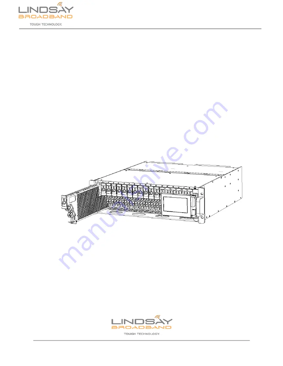
Application modules of LB-1000 can be installed in any of the general slots of the rack. Module
is inserted into the rack from the front part.
1)
Gently insert the LB-1000 application module into any general slot (labelled 01 to 18)
from the front of the chassis. Be careful to align the metal guide rails on the top and
bottom of the module to the chassis housing.
2)
Using the handle completely push the application module into the slot. Once the
module is completely inserted into the slot, the latch on the bottom of the module will
lock into place with the LB-1000 chassis securing the module in the rack. Ensure that
the application module is securely connected to the LB-1000-CH rear panel and F-
connectors. The application module will be automatically power “ON”. The Status
LED on the front of the module will turn ON and the module will show up on the
control module screen or web interface.
Figure 3: LB-1000 application module installation
3)
If the module hasn’t been properly connected to the LB-1000-CH it will not power up
and status LED will be OFF. In such a case, remove the application module from LB-
1000-CH slot and reinsert carefully as described in steps 1 and 2 above. See below
step for safely removing the module.
4)
To remove the application module from the slot, press down on the latch located in
the bottom front of the module. The application module will unlock from the LB-1000-
CH rack and module can be removed.
5)
Carefully clean all the fiber optic connectors and jumper cables. Use appropriate
cleaning swabs for fiber optic cables and connectors. Check for


