13
/23
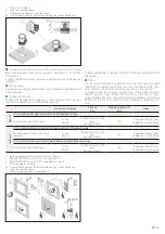
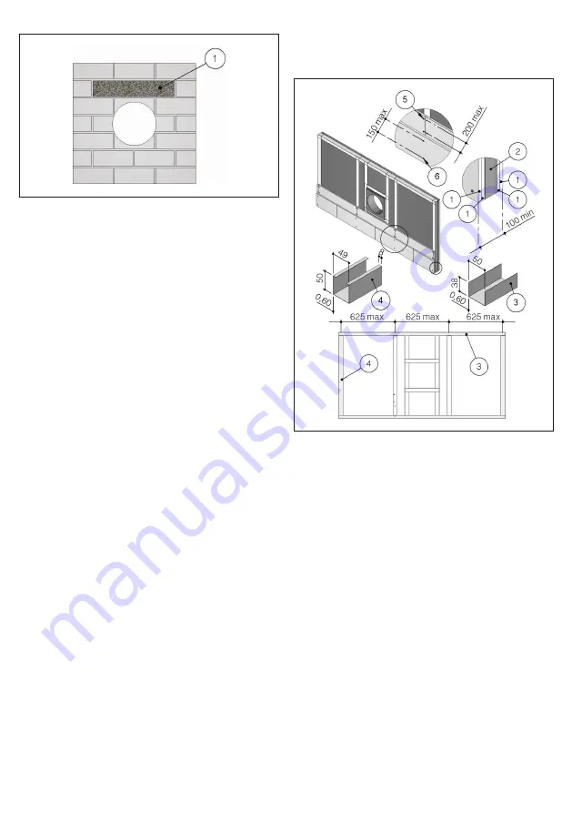
1. Reinforcing beam
Light plasterboard vertical walls
During testing, light plasterboard walls have been used with the fol-
lowing characteristics:
• U-shaped horizontal metal frame (50 mm) and C-shaped vertical
frame (49 mm) made from 0,6 mm thick sheet metal;
• Vertical profiles placed with a maximum spacing of 625 mm be-
tween each other;
• Rock wool filling which has density 80 kg/m³;
• Each side is made from two plasterboard layers 12,5 mm thick, un-
alinged to avoid alignment between the joints of the layer above
and below.
The following indications are given for the installation walls:
• metal profiles minimum width: 49 mm;
• metal profiles minimum thickness: 0,6 mm;
• vertical profiles placed with a maximum spacing of 625 mm be-
tween each other;
• vertical profile fixing with selfthreading screws or by clinching to
the bottom horizontal profile and insertion in the top horizontal
profile;
• profiles fixed using self-threading screws or by clinching on every
intersection.
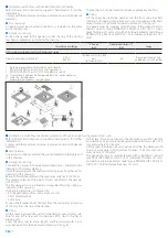
• installation of a frame around the damper with base and height
where shown in the installation instructions;
• rock wool filling which has minimum density 80 kg/m³:
• each side is made from two plasterboard layers 12,5 mm minu-
mum thick, unalinged to avoid alignment between the joints of
the layer above and below.
• the front plasterboards layers are fixed using long enough screws
to pass through the lower plasterboard and attach to the steel pro-
file underneath.
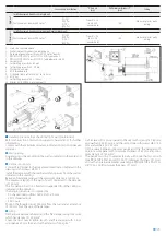
1. Plasterboard thickness 12,5 mm
2. Rock wool density up to 80 kg/m³ (optional)
3. Horizontal U-shaped profile
4. Vertical C-shaped profile
5. Self-drilling screw Ø 3,5 X 25 mm
6. Self-drilling screw Ø 3,5 X 35 mm
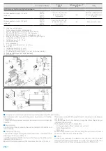
Light plasterboard vertical walls (Shaft wall)
The following indications are given for the installation walls:
• U-shaped horizontal metal frame (minimum width 50 mm) and
C-shaped vertical frame (minimum width 49 mm) made from
sheet metal (minimum thickness 0,6 mm);
• vertical profiles placed with a maximum spacing of 1000 mm be-
tween each other;
• vertical profile fixing with selfthreading screws or by clinching to
the bottom horizontal profile and insertion in the top horizontal
profile;
• profiles fixed using self-threading screws or by clinching on every
intersection.
• installation of a frame around the damper with base and height
where shown in the installation instructions;
• one side is made from two plasterboard layers 20 mm minumum
thick, unalinged to avoid alignment between the joints of the layer
above and below;
• the front plasterboards layers are fixed using long enough screws
to pass through the lower plasterboard and attach to the steel pro-
file underneath.


