8
/23
Motorized fire dampers electical wiring
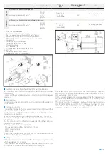
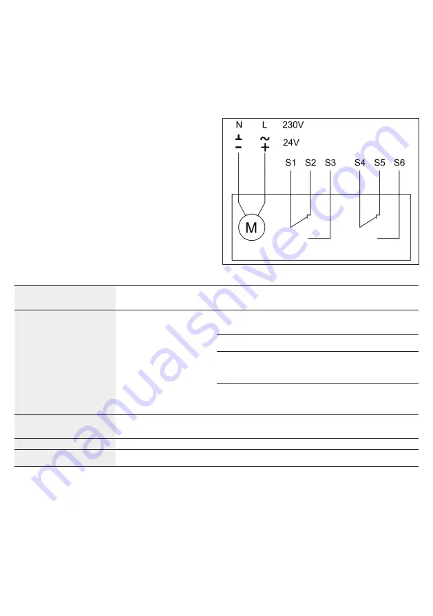
To connect the dampers to the power supply, proceed as follows:
• Check that the voltage and electrical frequency are equivalent to
those of the motor of the servomotor (check the motor's informa-
tion label);
• Make the connections as shown in the below diagram.
Microswitches position for motorized version
24V AC/DC power supply
/- Negative (DC) or neutral (AC) black wire
~/+ Positive (DC) or phase (AC) red wire
230V AC power supply
N Neutral blue wire
L Phase brown wire
Microswitches position contacts
S1 Common closed damper microswitch
S2 Normally closed, closed damper microswitch
S3 Normally opened, closed damper microswitch
S4 Common open damper microswitch
S5 Normally closed, open damper microswitch
S6 Normally opened, open damper microswitch
Electrical specifications
Manual and compact manual
Manual with magnet
Belimo motorized version
Siemens motorized version
Voltage and power consumption
-
Magnet (WH25MR/MI):
24/48 V DC (automatic voltage switching
on S0-25 electric board for 24 V magnet)
Power interrruption magnet (MR):
P = 1,6 W
Power input magnet (MI):
P = 3,4 W
Motor 24 V AC/DC (WH25VSB):
Belimo BFL24T
Opening: 2,5 W
In stand-by: 0,8 W
Motor 230 V AC (WH25DSB):
Belimo BFL230T:
Opening: 3,5 W
In stand-by: 1,1 W
Motor 24 V AC/DC (WH25VSS):
Siemens GRA126
Opening: 3,5 W
In stand-by: 2 W
Motor 230 V AC (WH25DSS):
Siemens GRA326
Opening: 4,5 W
In stand-by: 3,5 W
Microswitches position contacts
Manual control version:
12 V DC / 2 A
125 V AC / 0,1 A
Motorized version:
Siemens: AC 24 V…230 V / 6 (2) A
Belimo: DC 5 V…AC 250 V / 1 mA…3 A (0,5 A)
Blade closing time
Spring: 1 s
motor: < 30 s
Protection degree
IP42
IP42 MAGNETIC VERSION
IP54 MOTORIZED VERSION


