


8
/15
and verifying the correct movement of the blade and the correct
functioning of the microswitches (limit switches).
• If the damper is not connected to a remote control or command
system, manually execute an opening and closing test and check
the correct movement of the blade and the correct functioning of
the microswitches (limit switches) if present.
Together with the control activities, it is recommended to visually
verify the absence of corrosion, the integrity of the electrical wiring
and the sealing of the construction support.
Damper cleaning is included in the ordinary maintenance activities
of the ventilation ducts.
Fire dampers can be cleaned with a dry or wet cloth.
In the case of resistant dirt, it is possible to use normal household
detergents.
If prescribed for the type of building, it is possible to use disinfectant
detergents.
The use of detergents or mechanical abrasive cleaning systems is not
permitted.
These indications comply with the standards EN 15650 annex D and
EN 15423 annex C.
Repair
For safety reasons, repair activities involving fire-fighting compo-
nents must be carried out only by qualified personnel.
Only original spare parts supplied by the fire damper manufacturer
must be used.
A functional test must be performed after each repair.
.
At the end of the inspection, cleaning or repair operations, check that
the fire damper is in the normal operating position.
Keep records of all inspections, repair activities, any problems en-
countered and their resolution.
This practice, even when not mandatory, is very useful in practice.
Disposal
Disposal in case of destruction must be carried out in accordance
with national legislation. For electrical and electronic parts also refer
to EU Directive 2011/65.
INSTALLATION
The sizes shown are in mm.
It is recommended to perform a functional test before Installation to
exclude possible damage during transport and another test immedi-
ately after installation to exclude accidental damage to the product
and interference with mounting components.
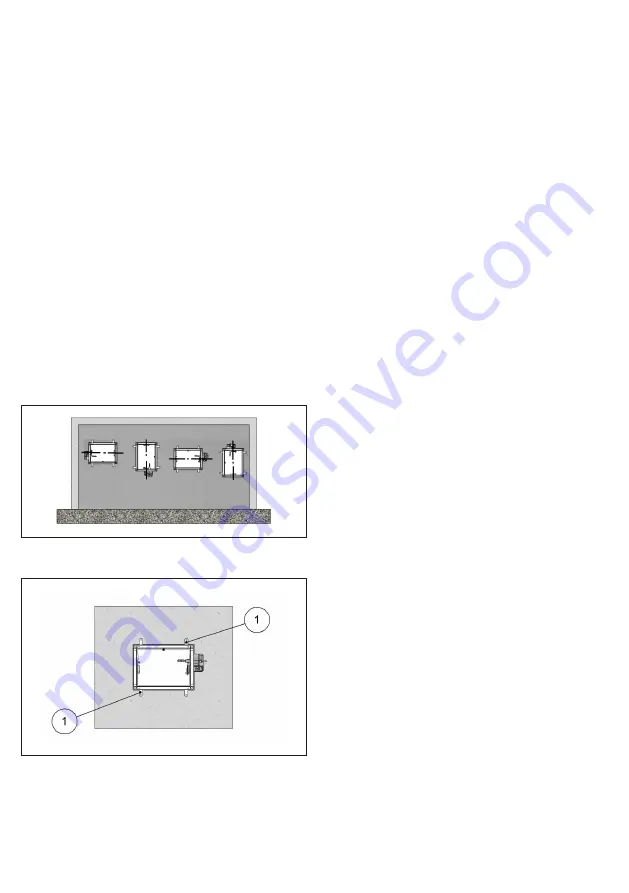
Blade rotation axis positioning
The fire damper can be installed both with the blade axis positioned
vertically or horizontally.
Positioning brackets before fixing
1. Positioning brackets
Installation of flexible connectors in order to balance out the
ventilation ducts expansion
CAUTION: Refer anyway to law and national standardization.
Flexible connectors compensate any duct thermal expansion and
wall bending in case of fire.
Flexible connectors are used to limit fire damper stresses due to ex-
ternal forces in case of fire and to preserve fire resistance class.
In general it is always appropriate the use of flexible connectors for
the followings installations:
– light walls;
– Plasterboard and rock wool or Fire Batt (Weichschott) sealing;
– Applique fixing system.
Flexible connector must be normal flammability and in case of fire
the grounding bonding should disconnet to guarantee the com-
plete separation between fire damper and connected air duct.
When flexible connectors made of conductive material (e.g. alumi-
num) are used, no additional grounding bonding is required.
Despite flexible connector installation, the fire damper must be in-
stalled in the construction support so that its weight does not affect
damper’s installation position both during normal operation and in
case of fire.
It is recommended not to compress flexible connectors in the in-
stallation phase.
Flexible connector must be at least 100mm long and in order that
possible duct thermal expansions are balanced.
Take care that the flexible connector does not interfer with opening
/ closing movement of the blade.
Transfer Application (application not connected to air ducts on
one or both sides)
Following tests performed as per EN 1366-2, section 6.3.6 Standard,
it is possible to install the fire damper free from air duct from one or
both sides.
• Attention: fire resistance classification for transfer application is
conform to section Fire resistance classification according to EN
13501-3-2009 limited to EI 120S if the ducted classification is high-
er.
• End cap with mesh shall be mounted on the side not connected
to air duct.
• End cap with mesh is made from galvanized steel sheet and in-
cludes nuts and screws for fixing on fire damper.
• End cap with mesh is supplied loose from the fire damper.


