H-3
TIG Svetsning
I maskinens utrustning ingår inte den TIG brännare som
krävs för TIG svetsning. Denna kan emellertid köpas
separat. Anslut TIG brännaren till den negativa (-)
terminalen på maskinen och återledarkabeln till
maskinens positiva (+) terminal. Anslut hankontakten så
att stiftet på kopplingen äntrar slitsen på honkontakten
på strömkällan. Dra åt cirka ett ¼ varv medurs. Dra inte
åt för hårt.
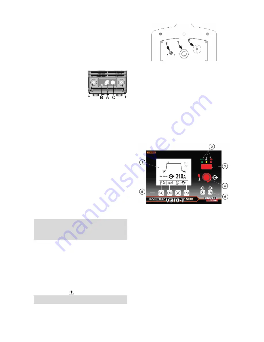
Anslut gasslangen från TIG
brännaren till
snabbkopplingen (B) på
maskinens front. Om så
krävs, finns en extra
snabbkoppling för TIG
brännarens gasslang med
maskinen. Därefter, anslut
nippeln på maskinens baksida till regulatorn på
gasflaskan. En gas-slang och nippel med mutter finns
med maskinen. Anslut TIG brännarens avtryckare till
uttaget (A) på maskinens front. Anslut vattenslangarna
från TIG-brännaren till snabbkopplingarna på
kylaggregatet om maskinen är utrustad med ett Coolarc
kylaggregat.
Anslutning av Fjärrkontroll
Se avsnittet om tillbehör för en förteckning över
fjärrkontroller. Om en fjärrkontroll används ansluts den
till uttaget (C) på maskinens front.
Optional COOL-ARC 35 Water Cooler
The optional Cool-Arc 35 water cooler is designed to
operate in communication with the V310-T AC/DC.
Refer to the Cool-Arc 35 operator manual for installation
instructions and a complete description of its operation.
When the V310-T AC/DC is powered ON the Cool-Arc35
will automatically power ON as well. The Cool-Arc35
monitors pressure and temperature and will adjust the
pump speed accordingly to cool the torch. If a blockage
of coolant or loss of coolant is sensed both the Cool-Arc
35 and V310-T AC/DC will display an error and turn off
the V310-T AC/DC’s output.
IMPORTANT: If the Cool-Arc 35 water cooler is
connected to the V310-T AC/DC and an air cooled torch
is connected instead of a water cooled torch the Cool-
Arc 35 will sense a coolant blockage resulting in a cooler
error.
In this case the cooler can be turned to the "off mode" by
depressing and holding the push button on the cooler
until the cooler’s display reads "oo". To turn the cooler
back on you can depress and hold the Cool-Arc 35 push
button until the cooler’s digital display reads coolant
temperature in degrees Celsius. Turning the V310-T
AC/DC off and on again will automatically turn the water
cooler back on as well.
Rear Control Panel
VARNING
I1: Off/On switch turns on the electric power to the
welder. It has two positions, "O" off, and "I" on.
1. Supply
cable.
2. Gas
attachment.
l1: Power Switch.
•
With "l1" in the "I"(ON) position, the welding
machine is operational and there is voltage between
the positive (+) and negative (-) Terminals in stick
welding. In TIG, the welding process needs a
trigger closure command at the remote control
connection (Usually via an Arc Start Switch or Foot
Amptrol).
•
The welder is connected to the supply even if the
"l1" (Power Switch) is in the "O" (Off) position, and
therefore there are electrically live parts inside the
power source. Carefully follow the instructions
given in this manual.
User Interface Overview and Operation
Figure B.3
The V310-T AC/DC User interface consists of the
following (Refer to Figure B.3):
1. Dynamic LCD Display
2. Status LED Lights
a) VRD On (Voltage Reduction Device) - If the
voltage reduction device is enabled from the
setup menu this green LED will illuminate when
the open circuit voltage is present at the output
terminals and held below the VRD threshold
limit. If the VRD is disabled or the unit is
welding, it will not illuminate.
b) General Alarm - Yellow LED which is lit when
faults exist with the power source or optional
cooler, such as over temperature, coolant
blockage, etc.
c) Output On (No VRD) - This status light will
illuminate red whenever the output in
electrically hot and the voltage level is above
the VRD threshold value.
3. 7-segment LED display (H)
4. Push button / Rotary Encoder
5. Mode Push buttons (A-D)
a) Weld
Mode
(A)
b) Trigger
Mode
(B)


