NOTE:
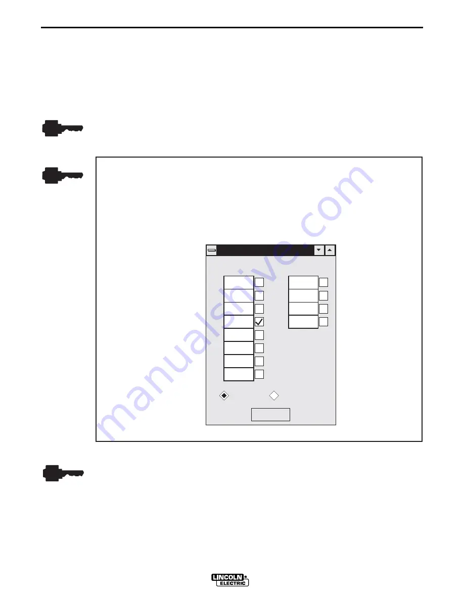
You can edit one or more workpoints to values other than the defaults.
However, the listing of wire feed speeds displayed must be the same or
increasing from top to bottom. All twelve wire feed speeds must be assigned
values, but multiple workpoints can share the same value.
The reason you would edit multiple workpoints to the same value would be to
limit the range of WFS or to develop fewer than twelve workpoints.
A.4.2 CUSTOMIZING THE WAVE SHAPE
If customizing your first wave shape, perform the wave shaping exercises provided at the back of
this section to get thoroughly acquainted with wave shaping. Thereafter, refer to the following
wave shaping procedure.
1. Select a Workpoint
a. Select a workpoint from the Wire Feed Speed pulldown menu. The first workpoint selected
should be in the midrange of the expected Wire Feed Speeds to be used for the weld
application. If you are uncertain of the WFS range, we recommend selecting 150 or 200
in./min. as a first workpoint.
Appendix A
A-7
PULSE WAVE SHAPING PRINCIPLES
WAVE DESIGNER
WorkPoint Editor
WorkPoint Editor
1
0
2
3
4
5
6
7
8
9
10
11
50
700
80
850
110
1000
150
1200
205
300
400
600
inch / min
meter / min
Go Figure
28750032
b. Set the welding machine’s wire feed speed equal to the selected workpoint setting.
c. Verify that the power source control box Weld Mode is set for an OFF readout at the LED
display and that the arc control is OFF.
Summary of Contents for WAVE DESIGNER
Page 2: ......
Page 6: ...iv iv LICENSE INFORMATION WAVE DESIGNER...
Page 26: ...3 14 Section 3 SOFTWARE OPERATION WAVE DESIGNER...
Page 30: ...4 4 Section 4 ARCSCOPE WAVE DESIGNER...
Page 32: ...5 2 Section 5 TROUBLESHOOTING WAVE DESIGNER...
Page 54: ...A 22 Appendix A PULSE WAVE SHAPING PRINCIPLES WAVE DESIGNER...
Page 74: ...INDEX Index 4 WAVEDESIGNER...


