Section 3
3-3
SOFTWARE OPERATION
WAVE DESIGNER
5.
Optional Windows
The optional window buttons open additional windows used during
wave shaping. Optional windows in the pulse Waveform Editor include Start, Adapt, Short,
End, and About. Details about the use of most optional windows is covered in the applicable
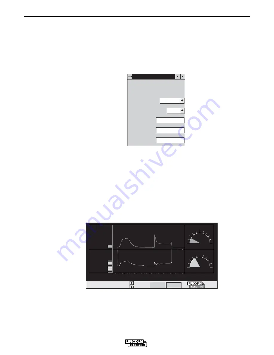
appendix (i.e. Appendix A for Pulse Wave Shaping). We use the About window shown in
Figure 3-3 to record descriptive weld application data for custom wave shape files. This
information is stored with the program in the computer and in the Power Wave.
FIGURE 3-3. THE “ABOUT” EDIT WINDOW.
6.
Wave Designer Status Bar
This status bar provides a scrolled listing of recent program
events, error conditions, etc. Use the arrow keys
∂
ƒ
to scroll through the listings. The status
bar includes three system status indicators: on line/off line, standby/welding, and
adaptive/non-adapt. The adaptive indicator is also a button that toggles between the
adaptive and non-adaptive mode.
7.
Volts/Amps Display
The Volts/Amps display, Figure 3-4, provides real time, oscilloscope
type displays of the voltage and amperage outputs from the connected power source.
Smaller display monitors (640 x 480 pixels or less) will not show the volts/amps display.
FIGURE 3-4. TYPICAL VOLTS/AMPS DISPLAY.
About the Procedure
About the Procedure
Process Type
GMAW
Wire Type
Wire Size
Process Name
27850007
Steel Pulse A
Procedure
Gas
super GAS
.035 Steel
6.3mm
Other
On Line
Adaptive
27850008
Welding
Summary of Contents for WAVE DESIGNER
Page 2: ......
Page 6: ...iv iv LICENSE INFORMATION WAVE DESIGNER...
Page 26: ...3 14 Section 3 SOFTWARE OPERATION WAVE DESIGNER...
Page 30: ...4 4 Section 4 ARCSCOPE WAVE DESIGNER...
Page 32: ...5 2 Section 5 TROUBLESHOOTING WAVE DESIGNER...
Page 54: ...A 22 Appendix A PULSE WAVE SHAPING PRINCIPLES WAVE DESIGNER...
Page 74: ...INDEX Index 4 WAVEDESIGNER...


