background image

EX350i

A-1

INSTALLATION   

A-1

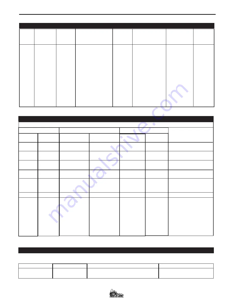
TECHNICAL SPECIFICATIONS - 

RED-D-ARC EX350i

INPUT AC VOLTAGE & DC OUTPUT

Product

Ordering

Input AC

Rated DC Output

Output

Weight

Dimensions

Open 

Name Information

Voltage

Amps/Volt

Range

with Cord

HxWxD

Circuit

/Duty Cycle

(continuous)

Voltage

200

208-230/

14.8” x 13.3” x

380-400/

350A / 34V / 60%

(373 x 338 x

415-460/

AMPS

(84.0 lbs)

27.8”*

EX350i

K1728-2

575

5-425

(38.0 kg.)

(373 x 338 x

80 VDC

1& 3 Phase  300A / 32V /100%

706*)mm

60/50 Hz

* Overall Length Including Handle, 27.8” (706mm)

Voltage

200

208
230
380

400

415
460
575

200
208
230
380
400
415
460
575

Phases

1

1
1
1

1

1
1
1

3
3
3
3
3
3
3
3

300Amps @

32Volts(100%)

Not

Recommended

76
69

Not

Recommended

Not

Recommended

41
36
31

41
39
36
23
22
22
19
16

350Amps @

34Volts(60%)

Not

Recommended

94
85

Not

Recommended

Not

Recommended

64
42
37

50
50
42
28
27
26
23
18

Line Cord

AWG

2
4

---

6
8
8

8
6
8
8
8
8
8
8

Fuse size

---

125A
125A

---

---

80A
70A
50A

80A
80A
70A
50A
50A
50A
50A
35A

EX350i INPUT CURRENT

OUTPUT CABLES, CONNECTIONS AND LIMITATIONS

Recommended Fuse Sizes Base On The U.S. National Electrical Code And Maximum Machine Outputs

Input 50/60 Hz

Output

Recommended

Note 1. Not rated is indicated by 4-x’s in the box on the rating plate.
Note 2. When operating on these inputs, the line cord should be changed to an input conductor of 6 AWG or larger.

Select The output cable size based upon the following chart.
Cable sizes for Combined Length of Electrode and Work Cable (Copper) 75C rated:

DUTY CYCLE

100%

60%

CURRENT

300
350

LENGTH UP TO 200FT.(61m)

1/0
1/0

200-250 FT. (61-76m)

1/0
2/0

Notes

Note 1

Note 2
Note 2
Note 1

Note 1

Note 2

Note 2
Note 2

Summary of Contents for Red-D-Arc EX350i

Page 1: ... safety in mind However your overall safety can be increased by proper installation and thoughtful operation on your part DO NOT INSTALL OPERATE OR REPAIR THIS EQUIPMENT WITHOUT READING THIS MANUAL AND THE SAFETY PRECAUTIONS CONTAINED THROUGHOUT And most importantly think before you act and be careful For use with machines having Code Numbers 10945 North America s Largest Fleet of Welding Equipmen...

Page 2: ...R WEARERS SHOULD CONSULT WITH THEIR DOCTOR BEFORE OPERATING Read and understand the following safety highlights For additional safety information it is strongly recommended that you purchase a copy of Safety in Welding Cutting ANSI Standard Z49 1 from the American Welding Society P O Box 351040 Miami Florida 33135 or CSA Standard W117 2 1974 A Free copy of Arc Welding Safety booklet E205 is availa...

Page 3: ...rical earth ground 3 f Maintain the electrode holder work clamp welding cable and welding machine in good safe operating condition Replace damaged insulation 3 g Never dip the electrode in water for cooling 3 h Never simultaneously touch electrically hot parts of electrode holders connected to two welders because voltage between the two can be the total of the open circuit voltage of both welders ...

Page 4: ...event the welding sparks from starting a fire Remember that welding sparks and hot materials from welding can easily go through small cracks and openings to adjacent areas Avoid welding near hydraulic lines Have a fire extinguisher readily available 6 b Where compressed gases are to be used at the job site special precautions should be used to prevent hazardous situations Refer to Safety in Weldin...

Page 5: ...s et non inflammables 4 Des gouttes de laitier en fusion sont émises de l arc de soudage Se protéger avec des vêtements de protection libres de l huile tels que les gants en cuir chemise épaisse pan talons sans revers et chaussures montantes 5 Toujours porter des lunettes de sécurité dans la zone de soudage Utiliser des lunettes avec écrans lateraux dans les zones où l on pique le laitier 6 Eloign...

Page 6: ...he information must be followed to avoid minor personal injury or damage to this equipment CAUTION Please Examine Carton and Equipment For Damage Immediately When this equipment is shipped title passes to the purchaser upon receipt by the carrier Consequently Claims for material damaged in shipment must be made by the purchaser against the transportation company at the time the shipment is receive...

Page 7: ... Processes B 9 _______________________________________________________________________ Accessories Section C Options Accessories C 1 Field Installed Options C 1 Quick Disconnect Plugs C 1 ________________________________________________________________________ Maintenance Section D Safety Precautions D 1 CAPACITOR DISCHARGE PROCEDURE D 1 VISUAL INSPECTION D 1 ROUTINE MAINTENANCE D 1 PERIODIC MAINT...

Page 8: ...6 23 22 22 19 16 350Amps 34Volts 60 Not Recommended 94 85 Not Recommended Not Recommended 64 42 37 50 50 42 28 27 26 23 18 Line Cord AWG 2 4 6 8 8 8 6 8 8 8 8 8 8 Fuse size 125A 125A 80A 70A 50A 80A 80A 70A 50A 50A 50A 50A 35A EX350i INPUT CURRENT OUTPUT CABLES CONNECTIONS AND LIMITATIONS Recommended Fuse Sizes Base On The U S National Electrical Code And Maximum Machine Outputs Input 50 60 Hz Out...

Page 9: ...ng elit ed diam nonum my nibh euismo d tincidu nt ut elit ed diam nonum my nibh euismo d tincidu nt ut laoreet dolore magna aliquam erat laoreet dolore magna aliquam erat Lorem ipsum dolor sit amet consec tetuer adipisc ing Lorem ipsum dolor sit amet consec tetuer adipisc ing elit ed diam nonum my nibh euismo d tincidu nt ut elit ed diam nonum my nibh euismo d tincidu nt ut laoreet dolore magna al...

Page 10: ...ode Connect the work lead to the other terminal Set the meter polarity switch on the front of the EX350i to coincide with wire feeder polarity used The wire feeder will now display the welding volt age If a remote control is to be used with the LN 742 use a K864 adapter to connect the feeder and a K857 remote to the 14 pin wire feeder connector on the front of the EX350i Cobramatic Connection Inst...

Page 11: ...200 amps not 300 amps from one and 100 amps from the other This will minimize nuisance shutdown conditions In general more than two machines in parallel will not be effective due to the voltage require ments of procedures in that power range To set machine outputs start with output control pots and arc control pots in identical positions Use the output control pots to balance the currents and main...

Page 12: ...ink indicat ing that the machine is in the Hold period 2 VOLT METER Prior to CV operation current flow the meter dis plays desired preset voltage value 5V Prior to STICK or TIG operation the meter displays the Open Circuit Voltage of the Power Source or four dashes if the output has not been turned on During welding this meter displays actual average volts After welding the meter holds the actual ...

Page 13: ...f carbon used The recommended maximum size carbon is 5 16 The Hot Start control regulates the starting current at arc initiation Hot Start can be adjusted from min imum 0 with no additional current added at arc start to maximum 10 with double the preset cur rent or 425 amps max of machine added for the first second after arc initiation The Arc Control regulates the Arc Force to adjust the short ci...

Page 14: ...fter the arc switch has been opened and the post flow time expired If the Weld Terminals are turned ON then the sole noid will open when the electrode is touch to the work The electrode needs to remain in contact with the work to allow for gas coverage before attempting to start the arc The solenoid will close after the arc has been broken and the post flow time expired CV WIRE The CV WIRE mode fe...

Page 15: ... compressed air EX350i Pulsed Modes In Pulse Modes The work point will be in the Amps window and should be set close to the wire feed speed of the wire feeder in inches per minute The Volts window will have SPd displayed indicating Wire Feed Speed Once current starts flowing and during the 5 second Hold feature the displays will show amps and volts Pulse Mode features that are displayed while sele...

Page 16: ...arc length is too short turn the Output knob up If the arc length is too long turn the Output knob down The Arc Control which is displayed in the right digital window can be used to fine tune the arc length and characteristics 5 After all adjustments have been made press and hold the Memory button until the display changes The right and the left window will display a memory position lets say M1 or...

Page 17: ...h low OCV Mid to Max range High frequency assisted starting with adjustable OCV up to 70 volts GMAW CV 10 45 volts The GMAW CV mode is the best selection for general MIG welding Metal core and gas shielded applications Arc Control Pinch Min min pinch softest arc Max max pinch crispest arc FCAW SS 10 45 volts The FCAW SS mode is designed for Self Shielded Innershield products that require tight vol...

Page 18: ...s similar to the Power Wave series As Arc Control is increased the frequency is increased and the background reduced Decreasing Arc Control will reduce frequency and increase background current Arc Control acts to fine tune the arc plasma to the specific application Preferred gas selections Steel Argon Blends Argon with CO2 additions from 2 to 20 or Oxygen additions from 2 to 5 Stainless Argon Ble...

Page 19: ...in amphenols If a remote is not connected to the 3 pin amphenol then the remote will default to the 14 pin amphenols if a remote is connected to one of the 14 pin amphenols If a remote control is connected to any of the amphenols the WELD TERMINAL control will default to REMOTE If there are not any remote control devices attached the WELD TERMINAL con trol will default to ON CC Stick modes The rem...

Page 20: ... 42 VAC supply is rated at 5 5 amps and is protected by a 6 amp breaker located by the amphenol 24 VAC supply is rated at 5 5 amps and is protected by a 6 amp breaker located by the amphenol LIMITATIONS The EX350i is not recommended for processes other than those listed The EX350i can only be used with the recommend ed equipment and options RECOMMENDED PROCESSES Properly equipped the EX350i suppor...

Page 21: ...ge K1499 1 DH 10 Bench Model K1521 1 DH 10 Generic 16ft Boom Package K1853 1 Cobramatic Not recommended for pulse welding FIELD INSTALLED OPTION K1762 2 TIG Gas Control Kit K1763 1 Advanced Process Panel EX350i QUICK DISCONNECT PLUGS A quick disconnect system is used for the welding cable connections The K852 70 is designed to accept a welding cable size of 1 0 to 2 0 1 Remove 25mm 1 in of welding...

Page 22: ...s removed Thermal Protection Thermostats protect the machine from excessive operating temperatures Excessive temperatures may be caused by a lack of cooling air or operating the machine beyond the duty cycle and output rating If excessive operating temperature should occur the thermostat will prevent output voltage or current The meter will remain energized during this time Thermostats are self re...

Page 23: ...CAUSE lists the obvious external possibilities that may contribute to the machine symptom Step 3 RECOMMENDED COURSE OF ACTION This column provides a course of action for the Possible Cause generally it states to contact your local Lincoln Authorized Field Service Facility If you do not understand or are unable to perform the Recommended Course of Action safely contact your local Lincoln Authorized...

Page 24: ...rrent or duty cycle is too high Reduce output current duty cycle or both 3 There is internal damage to the power source Contact an autho rized Lincoln Electric Service facil ity 1 Make certain that the power switch is in the ON position 2 The circuit breaker in the recon nect area may have opened Reset Check input voltage sec tion below 3 Input voltage selection made improperly Power down check in...

Page 25: ...y no power to wire feeder 1 Check for proper fan operation If fan is not operating correctly the CB 2 amp breaker may have opened Check for an overload on the 115VAC Blow air in rear lou vers to remove dirt from around fan 2 Check for material blocking intake or exhaust louvers 3 Blow air in the rear louvers to clear dirt from the fan 1 Check circuit breakers by the wire feeder receptacles on the ...

Page 26: ... on the primary over Check the machine Self clearing as current fault interrupt possibly ground condition ceases caused by noise or a signal level If problem persists misc hardware fault 1 contact an authorized Lincoln Field Service Shop 43 CAP delta CAP A and B are out Check input power of balance reconnect to make sure the machine is connected for the input power being supplied 44 Main CPU probl...

Page 27: ... initial three second period are displayed for 1 sec ond each Weld mode is changing A constant voltage weld mode is selected machine output is off The numeric value in the right display is the work point A constant current weld mode is selected machine output is off The numeric value in the left display is either the work point or a work point limit depending on the weld mode and remote configura ...

Page 28: ...R A I G H T P L U G 1 4 P I N T O P O W E R S O U R C E C A B L E R E C E P T A C L E 6 S O C K E T C A B L E R E C E P T A C L E 1 4 S O C K E T T O 1 L N 7 W I R E F E E D E R S T O 1 K 8 5 7 R E M O T E C O N T R O L 2 K 9 6 3 H A N D A M P T R O L 3 K 8 7 0 F O O T A M P T R O L K 8 6 4 S T R A I G H T P L U G 1 4 P I N T O P O W E R S O U R C E K 8 7 6 C A B L E R E C E P T A C L E 6 S O C K ...

Page 29: ...r e f e e d e r ELECTRIC SHOCK CAN KILL I N V E R T E C W I T H 1 1 5 V A C S 1 9 4 0 4 N A W E L D I N G C A B L E M U S T B E S I Z E D F O R C U R R E N T A N D D U T Y C Y C L E O F A P P L I C A T I O N N B D I A G R A M S H O W S E L E C T R O D E P O S I T I V E T O C H A N G E P O L A R I T Y T U R N P O W E R O F F R E V E R S E E L E C T R O D E A N D W O R K C A B L E A T P O W E R S O ...

Page 30: ... C A B L E E F D A B C 7 7 7 6 7 5 S P A R E 4 2 2 1 8 2 8 1 4 2 4 1 G N D 3 1 3 2 N D N D R E M O V E 6 P I N P L U G F R O M K 4 3 2 C A B L E I N O R D E R T O C O N N E C T K 8 6 7 P L U G L A B E L E A C H L E A D A T H R U F A S T H E Y A R E R E M O V E D F R O M 6 P I N P L U G N E N E S P L I C E L E A D S A N D I N S U L A T E O n l y q u a l i f i e d p e r s o n s s h o u l d i n s t a...

Page 31: ...5 5 A M P 1 1 5 V A C 2 A M P I N V E R T E C F R A M E C O N N E C T I O N N D N D F O R W I R E F E E D E R S T H A T R E T U R N A S I G N A L F O R W E L D I N G O U T P U T U S E I S O L A T I O N R E L A Y T O C L O S E L E A D S 2 4 2 4 T O K 8 6 7 E L E C T R O D E C A B L E W I R E F E E D E R V O L T M E T E R C O N N E C T I O N C O N N E C T S T O W O R K T E R M I N A L O F I N V E R ...

Page 32: ... C Y C L E O F A P P L I C A T I O N N B D I A G R A M S H O W S E L E C T R O D E P O S I T I V E T O C H A N G E P O L A R I T Y T U R N P O W E R O F F R E V E R S E E L E C T R O D E A N D W O R K C A B L E A T P O W E R S O U R C E T O W O R K 1 4 P I N A M P H E N O L E L E C T R O D E C A B L E T O L N 2 5 L N 2 5 W I T H K 4 3 1 O P T I O N K 4 3 2 R E M O T E C O N T R O L C A B L E 6 P I...

Page 33: ... I T Y T U R N P O W E R O F F R E V E R S E E L E C T R O D E A N D W O R K C A B L E A T P O W E R S O U R C E E L E C T R O D E C A B L E T O L N 7 T O W O R K 1 4 P I N A M P H E N O L L N 7 C O N T R O L B O X P O W E R S O U R C E I N V E R T E C K 8 6 4 K 4 8 0 7 I N P U T C A B L E 1 4 P I N A M P H E N O L K 8 5 7 R E M O T E C O N T R O L K 9 6 3 H A N D A M P T R O L K 8 7 0 F O O T A M...

Page 34: ...not be accurate for all machines covered by this manual The specific diagram for a particular code is pasted inside the machine on one of the enclosure panels If the diagram is illegible write to the Service Department for a replacement Give the equipment code number G4208 ...

Page 35: ...SION PRINT F 8 EX350i M19527 6 01 14 79 12 44 3 44 21 06 27 82 5 50 10 00 MOUNTING HOLE LOCATIONS 13 10 1 4 20 NUT 4 PLACES NOTE MOUNTING SCREWS CANNOT PROTRUDE MORE THAN 0 5 INCHES INSIDE THE MACHINE 3 50 11 84 ...

Page 36: ...NOTES EX350I ...

Page 37: ...16 383 2259 and ask for the Welding School Registrar Lincoln Welding School BASIC COURSE 700 00 5 weeks of fundamentals There is a 10 discount on all orders of 50 00 or more for shipment at one time to one location Orders of 50 or less before discount or orders outside of North America must be prepaid with charge check or money order in U S Funds Only Prices include shipment by 4thClass Book Rate ...

Page 38: ...electrically live parts or electrode with skin or wet clothing Insulate yourself from work and ground No toque las partes o los electrodos bajo carga con la piel o ropa moja da Aislese del trabajo y de la tierra Ne laissez ni la peau ni des vête ments mouillés entrer en contact avec des pièces sous tension Isolez vous du travail et de la terre Berühren Sie keine stromführenden Teile oder Elektrode...

Page 39: ...gute Be und Entlüftung des Arbeitsplatzes Mantenha seu rosto da fumaça Use ventilação e exhaustão para remover fumo da zona respiratória Turn power off before servicing Desconectar el cable de ali mentación de poder de la máquina antes de iniciar cualquier servicio Débranchez le courant avant l entre tien Strom vor Wartungsarbeiten abschalten Netzstrom völlig öff nen Maschine anhalten Não opere co...

Page 40: ...s and Service through Subsidiaries and Distributors Worldwide Cleveland Ohio 44117 1199 U S A TEL 216 481 8100 FAX 216 486 1751 WEB SITE www lincolnelectric com World s Leader in Welding and Cutting Products ...

Reviews: