Lincoln Electric Power MIG 360MP Operator'S Manual Download Page 29

E-

1

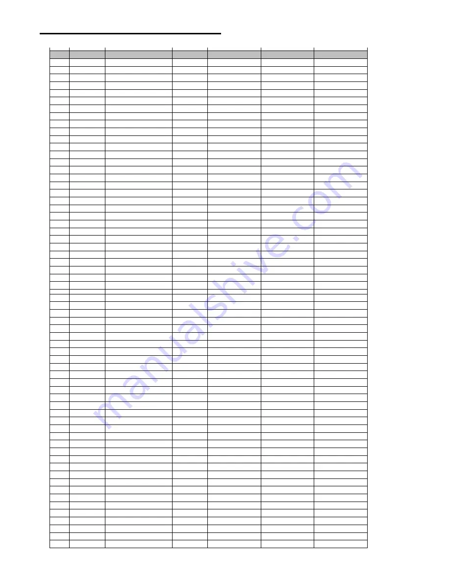
LIST OF LEGACY WELD MODES

Mode

Process

Procedure

Wire Size

Wire Type

Gas Type

ArcControl

1

SMAW

Stick General Purpose

Arc Force

2

SMAW

Stick Crisp

Arc Force

3

GTAW

Touch Start TIG

5

GMAW

CV MIG

Pinch

6

FCAW-S

CV Flux Core Self Shield

Pinch

7

FCAW-G

CV Flux Core Gas Shield

Pinch

8

GTAW

TIG Pulse (0.5 - 20 Hz)

Frequency

9

GTAW

TIG Pulse (20-300 Hz)

Frequency

10

GMAW

CV

.035in 

Steel

CO2

Pinch

11

GMAW

CV

.035in 

Steel

Argon Blends

Pinch

14

GMAW

Pulse

.035in 

Steel

Argon Blends

Arc Control

16

GMAW

Vertical Up Pulse

.035in 

Steel

Argon Blends

Frequency Offset

19

GMAW

Pulse

.045in 

Steel

Argon Blends

Arc Control

20

GMAW

CV

.045in 

Steel

CO2

Pinch

21

GMAW

CV

.045in 

Steel

Argon Blends

Pinch

23

GMAW

Vertical Up Pulse

.045in 

Steel

Argon Blends

Frequency Offset

28

GMAW

CV

.025in 

Steel

CO2

Pinch

29

GMAW

CV

.025in 

Steel

Argon Blends

Pinch

30

GMAW

Pulse

.025in 

Steel

Argon Blends

Arc Control

31

GMAW

CV

.035in 

Stainless

Pinch

32

GMAW

Pulse

.035in 

Stainless

Arc Control

33

GMAW

CV

.035in 

Stainless

He Ar CO2

Pinch

34

GMAW

Pulse

.035in 

Stainless

He Ar CO2

Arc Control

38

GMAW

Vertical Up Pulse

.035in 

Stainless

Frequency Offset

40

GMAW

Power Mode

®

 (Non Syn) 

Gas Shield

Pinch

41

GMAW

CV

.045in 

Stainless

Pinch

42

GMAW

Pulse

.045in 

Stainless

Arc Control

43

GMAW

CV

.045in 

Stainless

He Ar CO2

Pinch

44

GMAW

Pulse

.045in 

Stainless

He Ar CO2

Arc Control

48

Frequency Offset

61

GMAW

CV

.030in 

Stainless

Pinch

62

GMAW

Pulse

.030in 

Stainless

Arc Control

63

GMAW

CV

.030in 

Stainless

He Ar CO2

Pinch

64

GMAW

Pulse

.030in 

Stainless

He Ar CO2

Arc Control

71

GMAW

CV

3/64in 

Aluminum 4043

Argon

Pinch

72

GMAW

Pulse

3/64in 

Aluminum 4043

Argon

Arc Control

75

GMAW

CV

3/64in 

Aluminum 5356

Argon

Pinch

76

GMAW

Pulse

3/64in 

Aluminum 5356

Argon

Arc Control

81

GMAW

CV

.045in 

Metal Core

Argon Blends

Pinch

82

GMAW

Pulse

.045in 

Metal Core

Argon Blends

Arc Control

83

GMAW

CV

.052in 

Metal Core

Argon Blends

Pinch

84

GMAW

Pulse

.052in 

Metal Core

Argon Blends

Arc Control

85

GMAW

CV

1/16in 

Metal Core

Argon Blends

Pinch

86

GMAW

Pulse

1/16in 

Metal Core

Argon Blends

Arc Control

93

GMAW

CV

.030in 

Steel

CO2

Pinch

94

GMAW

CV

.030in 

Steel

Argon Blends

Pinch

95

GMAW

Pulse

.030in 

Steel

Argon Blends

Arc Control

97

GMAW

Pulse On Pulse

.030in 

Aluminum 4043

Argon

Modulation Freq

98

GMAW

Pulse On Pulse

.035in 

Aluminum 4043

Argon

Modulation Freq

99

GMAW

Pulse On Pulse

3/64in 

Aluminum 4043

Argon

Modulation Freq

101

GMAW

Pulse On Pulse

.035in 

Aluminum 5356

Argon

Modulation Freq

102

GMAW

Pulse On Pulse

3/64in 

Aluminum 5356

Argon

Modulation Freq

138

GMAW

CV

.040in 

Steel

CO2

Pinch

140

GMAW

Pulse

.040in 

Steel

Argon Blends

Arc Control

146

GMAW

CV

.030in 

Aluminum 4043

Argon

Pinch

147

GMAW

Pulse

.030in 

Aluminum 4043

Argon

Arc Control

148

GMAW

CV

.035in 

Aluminum 4043

Argon

Pinch

149

GMAW

Pulse

.035in 

Aluminum 4043

Argon

Arc Control

151

GMAW

CV

.035in 

Aluminum 5356

Argon

Pinch

152

GMAW

Pulse

.035in 

Aluminum 5356

Argon

Arc Control

190

GMAW

Pulse

.030in 

Si Bronze

Argon

Arc Control

191

GMAW

Pulse

.045in 

Si Bronze

Argon

Arc Control

192

GMAW

Pulse

.035in 

Si Bronze

Argon

Arc Control

196

GMAW

Pulse

.045in 

Copper

75He/25Ar

Arc Control

Argon Blends

Argon Blends

Argon Blends

Argon Blends

Stainless

.045in 

Vertical Up Pulse

GMAW

Argon Blends

Argon Blends

Argon Blends

Argon Blends

Summary of Contents for Power MIG 360MP

Page 1: ...Code Numbers 12910 Save for future reference Date Purchased Code ex 10859 Serial ex U1060512345 Power MIG 360MP Need Help Call 1 888 935 3877 to talk to a Service Representative Hours of Operation 8 00 AM to 6 00 PM ET Mon thru Fri After hours Use Ask the Experts at lincolnelectric com A Lincoln Service Representative will contact you no later than the following business day For Service outside th...

Page 2: ...N A LARGE ROOM OR OUTDOORS natural ventilation may be adequate if you keep your head out of the fumes See below USE NATURAL DRAFTS or fans to keep the fumes away from your face If you develop unusual symptoms see your supervisor Perhaps the welding atmosphere and ventilation system should be checked WEAR CORRECT EYE EAR BODY PROTECTION PROTECT your eyes and face with welding helmet properly fitted...

Page 3: ... hot engine parts and igniting Do not spill fuel when filling tank If fuel is spilled wipe it up and do not start engine until fumes have been eliminated 1 d Keep all equipment safety guards covers and devices in position and in good repair Keep hands hair clothing and tools away from V belts gears fans and all other moving parts when starting operating or repairing equipment 1 e In some cases it ...

Page 4: ...rm to ANSI Z87 I standards 4 b Use suitable clothing made from durable flame resistant material to protect your skin and that of your helpers from the arc rays 4 c Protect other nearby personnel with suitable non flammable screening and or warn them not to watch the arc nor expose themselves to the arc rays or to hot spatter or metal FUMES AND GASES CAN BE DANGEROUS 5 a Welding may produce fumes a...

Page 5: ...ent passing through lifting chains crane cables or other alternate circuits This can create fire hazards or overheat lifting chains or cables until they fail 6 h Also see item 1 c 6 I Read and follow NFPA 51B Standard for Fire Prevention During Welding Cutting and Other Hot Work available from NFPA 1 Batterymarch Park PO box 9101 Quincy MA 022690 9101 6 j Do not use a welding power source for pipe...

Page 6: ...ETS B 10 WIRE REEL LOADING READI REELS SPOOLS OR COILS B 10 TO START THE WELDER B 11 FEEDING WIRE ELECTRODE B 11 IDLE ROLL PRESSURE SETTING B 12 WIRE DRIVE CONFIGURATION B 12 MAKING A WELD B 12 AVOIDING WIRE FEEDING PROBLEMS B 13 FAN CONTROL B 13 INPUT LINE VOLTAGE PROTECTION B 13 WIRE FEED OVERLOAD PROTECTION B 13 WELDING THERMAL OVERLOAD PROTECTION B 13 OPTIONS ACCESSORIES SECTION C DRIVE ROLL K...

Page 7: ...urrent Range Continuous Maximum Open Circuit Voltage Welding Voltage Range 100 A 90 A GMAW GTAW DC SMAW RECOMMENDED INPUT WIRE AND FUSE SINGLE PHASE Input Voltage Frequency Hz Maximum Input Ampere and Duty Cycle Fuse or Breaker Size 208 1 50 60 230 1 50 60 Type S SO ST STO or extra hard usage input cord AWG IEC Sizes 6 16 mm 2 6 16 mm 2 10 6 mm 2 12 2 5 mm 2 460 1 50 60 575 1 50 60 91 A 40 83 A 40...

Page 8: ...flammable material away Do not weld on closed containers ARC RAYS can burn eyes and skin Wear eye ear and body protection Observe all safety information throughout this manual UNCRATING THE POWER MIG 360MP Cut banding and lift off cardboard carton Cut banding holding the machine to the skid Remove foam and corrugated packing material Untape accessories from Gas Bottle Platform Unscrew the two wood...

Page 9: ... supply is adequate for the voltage amperes phase and frequency specified on the welder rating plate Also be sure the planned installation will meet the U S National Electrical Code and local code requirements This welder may be operated from a single phase source or from two lines of a three phase source 2 POWER MIG 360MP has multiple input voltages specified on the nameplate The unit is shipped ...

Page 10: ...l tip of screw no longer protrudes into Gun Adapter Item 2 opening as seen from front of machine 3 Insert the male end of gun cable into the Gun Adapter Item 2 through the opening in front panel Make sure connector is fully inserted and tighten Hand Screw 4 Connect the Gun Trigger Connector from the gun and cable to the mating Receptacle inside the compartment located on the Front Panel Item 1 Mak...

Page 11: ...one side away from the outlet and open the cylinder valve for an instant This blows away any dust or dirt which may have accumulated in the valve outlet Be sure to keep your face away from the valve outlet when cracking the valve 4 Attach the flow regulator to the cylinder valve and tighten the union nut s securely with a wrench NOTE If connecting to 100 CO2 cylinder the regulator adapter provided...

Page 12: ...e prong plug and a 10 ft 3 1m work cable and clamp The POWER MIG 360MP features built in timer functions that provide variable burnback control a spot function a selectable 4 step trigger interlock and an adjustable Run In for wire starting optimization ARCFX technology comes standard and provides a way tp graphically communicate instant feedback of how the end user settings affect the weld outcom...

Page 13: ...Permits triggering the machine for MIG FCAW or aluminum MIG Connect the 4 pin connector present on the welding gun to the receptacle 7 Gun Connection Permits attachment of a MIG welding gun Ensure the gun is fully seated into the brass receptacle 8 Power Switch Permits turning the machine on or off 9 115V receptacle 10 Six Pin Connector Permits connecting a remote or TIG pedal 11 Output Studs Used...

Page 14: ...ching a work lead electrode stinger or the center wire drive polarity lead to DC negative polarity Rotate connector clockwise to lock into place 4 Positive Output Receptacle Permits attaching a work lead electrode stinger or the center wire drive polarity lead to DC positive polarity Rotate clockwise to lock into place 5 Thermal Breaker The POWER MIG 360 features a resettable 15 amp circuit breake...

Page 15: ...Applicable Select the thickness of the material to be welded Confirm polarity Turn off machine before changing polarity Adjust Wire Feed Speed and Voltage Trim accordingly Note The green section indicates the ideal range for the input welding parameters Back Home Select MIG Back Home Select MIG Material Steel Stainless Back Home Select MIG Wire Diameter 0 025 0 030 0 035 Back Steel 0 025 Ar CO2 Ho...

Page 16: ...rom 0 50 to 1 50 with a nominal value of 1 00 Trim values greater than 1 00 increase the arc length while values less than 1 00 decrease the length TIG GTAW Follow Ready Set Weld prompts and insert parameters per your application Use the right selector knob to adjust the weld current Note The green section indicates the ideal range for the input welding parameters If no foot pedal is connected you...

Page 17: ...d prior to wire feeding and establishing an arc PULSE Selecting this mode allows the user to toggle between standard CV TIG welding and Pulse TIG See section on Pulse TIG Mode RUN IN The Run In function offers the ability to set a wire feed speed from trigger until an arc is established that is independent of the Welding or Start wire feed speed Setting a Run In WFS lower than the welding WFS avoi...

Page 18: ...LANGUAGE The language of the text present in the user interface software can be modified The available FACTORY RESET The user interface software settings can be reset to the original factory settings SYSTEM INFO Information regarding the software revision of the user interface and the software revision of PROCESS ARC CONTROL SYNONYM SETTING APPLICATION AND RESULT SMAW STICK Arc Force Lower 1 to 10...

Page 19: ...h pulses are shown in Figure B 6 After a number N of such pulses depending on the wire feed speed used an identical number N of low energy pulses are performed These low energy pulses shown in Figure B 6 do not transfer any filler metal across the arc and help to cool the arc and keep the heat input low FIGURE B 7 The Peak Current Background Current and Frequency are identical for the high energy ...

Page 20: ...ure is not established the best way to determine the Power Mode Setting is by experimentation until the desired output result is established In the Power Mode two variables need to be set Wire Feed Speed Power Mode Trim Setting up a Power Mode procedure is similar to setting a CV MIG procedure Select a shielding gas appropriate for a short arc process For steel use 75 25 Ar CO2 shield gas For Stai...

Page 21: ...d remove it from the spindle 3 Place the Optional Adapter on the spindle 4 Re install the Retaining Collar Make sure that the Release Bar pops up and that the collar retainers fully engage the retaining ring groove on the spindle 5 Rotate the spindle and adapter so the retaining spring is at the 12 o clock position 6 Position the Readi Reel so that it will rotate in a direction when feeding so as ...

Page 22: ...e 2 While securely holding the electrode cut off the bent end and straighten the first six inches If the electrode is not properly straightened it may not feed properly through the wire drive system 3 Release the pressure on the idle roll by swinging the adjustable pressure arm down toward the back of the machine Lift the cast idle roll assembly and allow it to sit in an upright position Leave the...

Page 23: ...feed the wire electrode through the gun and cable and then cut the electrode within approximately 3 8 10 mm of the end of the contact tip 3 4 20 mm Outershield NOTE If set for slow run in when the trigger is pulled the wire feeder feeds wire at low speed regardless of the set wire feed speed until the welding arc starts or 1 second has elapsed This feature enhances starting and makes it easier to ...

Page 24: ...ine voltage exceeds 110 of rated input voltage the output will be reduced to the lower level to protect voltage rating of the capacitor bank Low Line Voltage You may not be able to get maximum output from the machine if the line voltage is less than rated input The unit will continue to weld but the output may be less than what is set WIRE FEED OVERLOAD PROTECTION The POWER MIG 360MP has solid sta...

Page 25: ...connector twist lock trigger connector fixed nozzle and insulator and includes a liner diffuser and contact tips for the wire sizes specified 1 Optional liners for different wire diameters are sold separately see table D 1 Maintenance Section 20 and 25 Magnum PRO Curve 300 Guns K2951 3 Magnum PRO Curve 300 20 K2951 4 Magnum PRO Curve 300 25 Requires K466 6 adapter and KP44 3545 25 liner MAGNUM GUN...

Page 26: ...n the welding application mmi Adjust the gas nozzle as appropriate for the GMAW process to be used Typically the contact tip end should be flush to 12 3 2 mm extended for the short circuiting transfer process and 12 3 2 mm recessed for spray transfer DRIVE ROLLS AND GUIDE PLATES After every coil of wire inspect the wire drive mechanism Clean it as necessary by blowing with low pressure compressed ...

Page 27: ...un and cable out straight on a flat surface Loosen set screw of the connector on the back end of the gun 4 Insert the untrimmed Liner into the back end of the gun 5 Seat Liner bushing into back of gun Secure Liner by tightening set screw Do not install the gas diffuser at this time 6 Lay the cable straight and trim Liner to 9 16 Remove burrs 7 Install insulator and secure the gas diffuser into the...

Page 28: ...ble assembly are straight 6 Using a stop watch pull the trigger for 10 seconds 7 Measure the wire from the tip of the torch to the end of the wire 8 The wire should measure just under 60 inches 9 Perform the gun calibration if the measurement is less than 57 or greater than 63 Calibrating Spool Gun 1 To calibrate the spool gun select Spool Gun from the Weld Process selection screen 2 Select the ap...

Page 29: ...O2 Arc Control 71 GMAW CV 3 64in Aluminum 4043 Argon Pinch 72 GMAW Pulse 3 64in Aluminum 4043 Argon Arc Control 75 GMAW CV 3 64in Aluminum 5356 Argon Pinch 76 GMAW Pulse 3 64in Aluminum 5356 Argon Arc Control 81 GMAW CV 045in Metal Core Argon Blends Pinch 82 GMAW Pulse 045in Metal Core Argon Blends Arc Control 83 GMAW CV 052in Metal Core Argon Blends Pinch 84 GMAW Pulse 052in Metal Core Argon Blen...

Page 30: ...s column describes possible symptoms that the machine may exhibit Find the listing that best describes the symptom that the machine is exhibiting Step 2 POSSIBLE CAUSE The second column labeled POSSIBLE CAUSE lists the obvious external possibilities that may contribute to the machine symptom Step 3 RECOMMENDED COURSE OF ACTION This column provides a course of action for the Possible Cause generall...

Page 31: ...or gas flow when gun trigger is pulled Fans operate normally 1 The thermostat may be tripped due to overheating Let machine cool Weld at lower duty cycle 2 Check for obstructions in air flow Check gun trigger connections See installation section 3 Gun trigger may be faulty Arc is unstable Poor starting 1 Check for correct input voltage to machine 2 Check machine reconnect panel is configured prope...

Page 32: ...eed and voltage are correct for the process being used 3 Make sure output polarity is correct for process being used 4 Check welding cables and gun assembly for loose or faulty connections FEEDING PROBLEMS No wire feed when gun trigger is pulled Fans run gas flows and machine has correct open circuit voltage 38V Max weld output 1 If the wire drive motor is running make sure that the correct drive ...

Page 33: ...er is pulled there may be a restriction in the gas supply line 3 The gun cable assembly may be faulty Check or replace 4 If gas solenoid does not operate when gun trigger is pulled the problem is within the POWER MIG 360MP 5 Make sure the gun is pushed all the way into gun mount and is properly seated SCREEN PROBLEMS Error code 213 is displayed on screen 1 Communication between display P C board a...

Page 34: ...hould be laid out relatively straight 2 Check the wire at the spool Make sure wire is not crossed and is de reeling properly 3 Increase wire feed speed to 350 400 ipm 1 Check torch cable for kinks Torch cable should be laid out relatively straight 2 Make sure liner conduit is inserted all the way into the rear wire drive so that it is up against the inner black plastic wire guide 3 Inner black pla...

Page 35: ...ength varies while welding arc length is not constant POSSIBLE CAUSE 1 Straighten the first six inches of the wire before feeding it into the rear wire drive 2 Make sure the torch drive rolls are tightened slightly to help the wire jump the gap 3 Slow down wire feed speed while pushing wire through torch liner Recommend setting 350 ipm 1 POWER MIG 360MP drive rolls set too tight The tension arm sh...

Page 36: ...Refer to the push pull connection kit for this spacer 2 POWER MIG 360MP drive rolls set too tight The tension arm should be set at 1 to 1 1 2 3 Push Pull torch drive rolls set too tight Refer to owners manual for proper setting 4 If pulse welding the trim value may be set too high 5 Clean or replace contact tip 1 Torch liner conduit not inserted all the way so that it is touching the inner black p...

Page 37: ... H7 H6 H5 H2 H4 H3 12 11 10 9 8 7 6 1 2 3 4 5 6 7 8 J7 1 2 3 4 5 6 J3 1 2 3 4 CONTROL BOARD J4 9 10 11 12 J1 J8 1 2 3 4 5 6 J9 1 2 3 4 5 6 J5 1 2 3 4 5 6 7 8 9 10 1 2 3 4 J11 1 2 J2 1 2 3 4 1 2 3 4 5 6 7 8 J6 303 304 301 302 R W R W COM VIN CAN_H CAN_L 411 412 508 509 608 607 1 2 3 4 5 6 7 8 TACH 603 605 604 602 601 411 412 W B 403 404 W R 401 402 J21 FAN B 3 2 1 B BR W 4 FAN C 2 1 B BR W 4 3 R R ...

Page 38: ...G 2 DIAGRAMS POWER MIG 360 Center of Gravity 12 38 37 38 40 35 13 33 37 30 18 00 16 88 11 62 ...

Page 39: ...This page has been left blank intentionally ...

Page 40: ...This page has been left blank intentionally ...

Page 41: ...This page has been left blank intentionally ...

Page 42: ...parts or electrode with skin or wet clothing l Insulate yourself from work and ground l No toque las partes o los electrodos bajo carga con la piel o ropa moja da l Aislese del trabajo y de la tierra l Ne laissez ni la peau ni des vête ments mouillés entrer en contact avec des pièces sous tension l Isolez vous du travail et de la terre l Berühren Sie keine stromführenden Teile oder Elektroden mit ...

Page 43: ... und Entlüftung des Arbeitsplatzes l Mantenha seu rosto da fumaça l Use ventilação e exhaustão para remover fumo da zona respiratória l Turn power off before servicing l Desconectar el cable de ali mentación de poder de la máquina antes de iniciar cualquier servicio l Débranchez le courant avant l entre tien l Strom vor Wartungsarbeiten abschalten Netzstrom völlig öff nen Maschine anhalten l Não o...

Page 44: ...stomer s particular purpose with respect to such information or advice As a matter of practical consideration we also cannot assume any respon sibility for updating or correcting any such information or advice once it has been given nor does the provision of information or advice create expand or alter any warranty with respect to the sale of our products Lincoln Electric is a responsive manufactu...

Reviews: