


B-8
OPERATION
POWER MIG
®
360MP
SPECIAL WELDING PROCESSES
PULSE WELDING
The pulsed-arc process is, by definition, a spray transfer process
wherein spray transfer occurs in pulses at regularly spaced
intervals. In the time between pulses, the welding current is
reduced and no metal transfer occurs.
Pulsed-arc transfer is obtained by operating a power source
between low and high current levels. The high current level or
“pulse” forces an electrode drop to the workpiece. The low
current level or “background” maintains the arc between pulses.
Pulsed MIG is an advanced form of welding that takes the best of
all the other forms of transfer while minimizing or eliminating their
disadvantages. Unlike short circuit, pulsed MIG does not create
spatter or run the risk of cold lapping. The welding positions in
pulsed MIG are not limited as they are with globular or spray and
its wire use is definitely more efficient. Unlike the spray arc
process, pulsing offers controlled heat input that allows better
welding on thin materials, lower wire feed speeds and leads to
less distortion and improved overall quality and appearance. This
is especially important with stain- less, nickel and other alloys that
are sensitive to heat input.
In Pulse MIG mode, arc control adjusts the background current
and frequency of the wave. When arc control goes up, the
frequency increases thus increasing the droplet transfer rate.
FIGURE B.5
PULSE-ON-PULSE
®
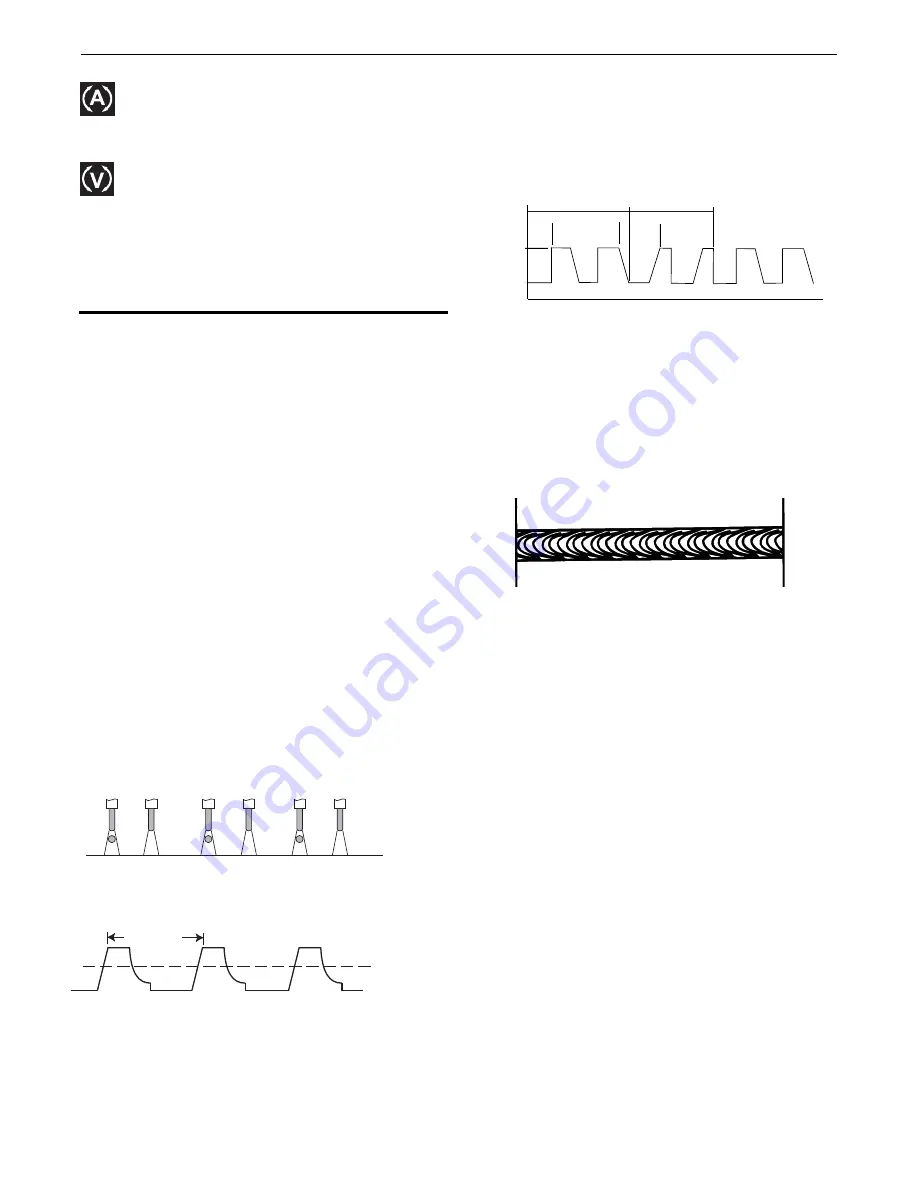
Pulse on Pulse™ is a Lincoln process specifically designed for use
in welding relatively thin (less than 1/4" thick) aluminum (See
Table B.3). It gives weld beads with very consistent uniform ripple.
FIGURE B.6
In Pulse on Pulse modes, two distinct pulse types are used,
instead of the single pulse type normally used in GMAW-P. A
number of high energy pulses are used to obtain spray transfer
and transfer metal across the arc. Such pulses are shown in
Figure B.6. After a number "N" of such pulses, depending on the
wire feed speed used, an identical number "N" of low energy
pulses are performed. These low energy pulses, shown in Figure
B.6, do not transfer any filler metal across the arc and help to cool
the arc and keep the heat input low.
FIGURE B.7
The Peak Current, Background Current, and Frequency are
identical for the high energy and low energy pulses. In addition to
cooling the weld down, the major effect of the low energy pulses
is that they form a weld ripple. Since they occur at very regular
time intervals, the weld bead obtained is very uniform with a very
consistent ripple pattern. In fact, the bead has its best appearance
if no oscillation of the welding gun ("whipping") is used.
Pulse Tig
Use Pulse TIG welding to help minimize burn through on thin
materials. It can help to increase travel speed and result in a
smaller bead width. Lower heat input may lessen warpage of
parts, especially stainless steel materials.
The Pulse TIG feature has a single knob control which sets the
Pulse Frequency over the range of .5-19.5 Hz (0.5-19.5 pulses per
second). Setting the frequency to “off”
disables the Pulse TIG
feature
. The
pulse setting automatically regulates the output
current between
the peak amperage, set by the max output
current between the
peak amperage, set by the max output
control and the remote
amtrol (if used), ad a background
amperage setting that is equal
to 60% of the peal amperage
setting. The Peak pulse % on-time is
fixed at 50%.
PEAK
AMPS
BACKGROUND
AMPS
TIME
HIGH HEAT
PULSES
LOW HEAT
PULSES
"N" PULSES
"N" PULSES
PEAK AMPS
FREQUENCY
SPRAY TRANSITION
CURRENT
EACH PULSE DELIVERS ONE DROPLET OF WELD MATERIAL
Current Calibration
-
Selecting current calibration mode
allows a service technician the ability to calibrate the
machine's output current. See Maintenance section for more
details.
Voltage
Calibration
-
Selecting voltage calibration mode
allows a service technician the ability to calibrate the
machine's output voltage. See Maintenance section for more
details.


