


English
English
1
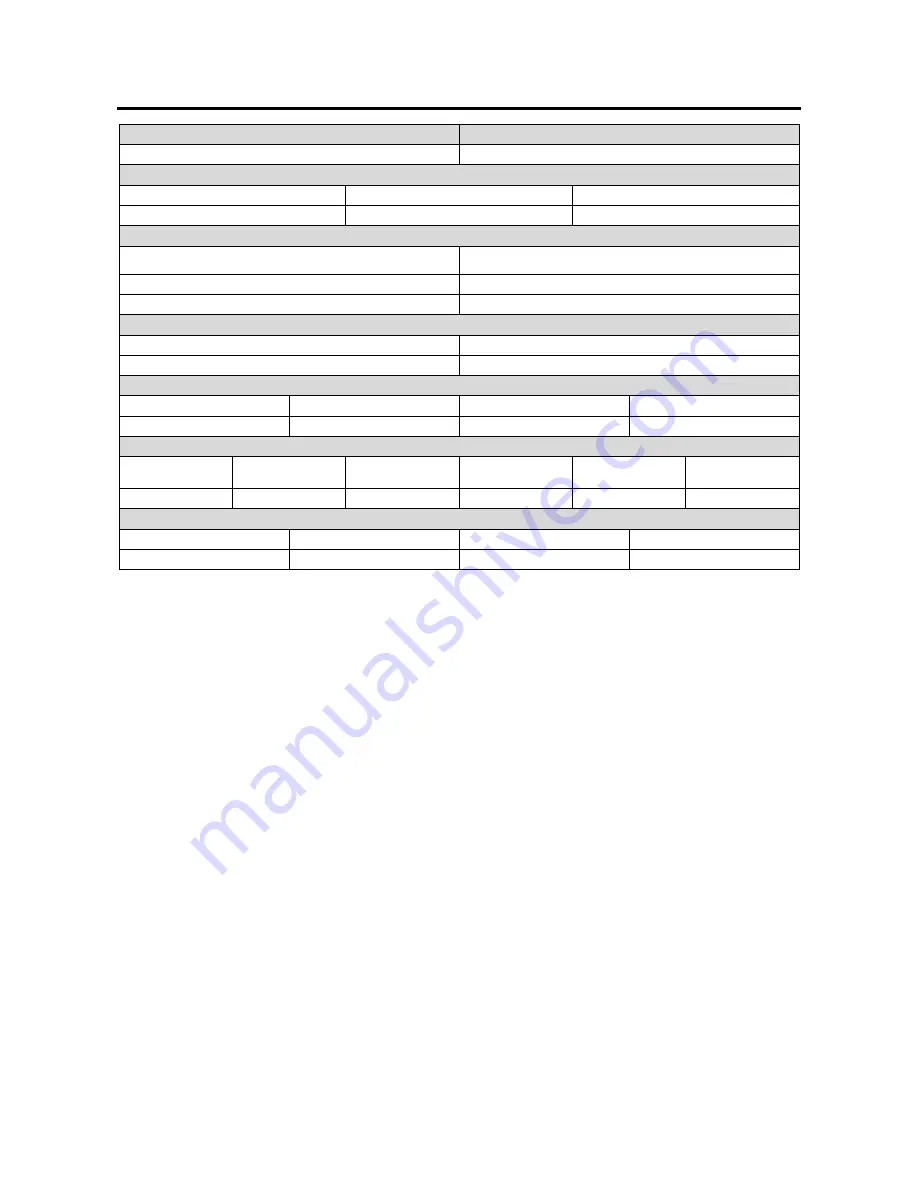
Technical Specifications
NAME
INDEX
PF41 K14163-1
INPUT
Input Voltage U
1
Input
Amperes
I
1
EMC
Class
40Vdc 4A A
RATED OUTPUT
Duty Cycle 40°C
(based on a 10 min. period)
Output Current
100% 385A
60% 500A
OUTPUT RANGE
Welding Current Range
Peak Open Circuit Voltage
5 ÷ 500A
113Vdc or Vac peak
DIMENSION
Weight Height Width Length
18 kg
460 mm
300 mm
640 mm
WIRE FEED SPEED RANGE / WIRE DIAMETER
WFS Range
Drive Rolls
Drive roll
diameter
Solid Wires
Aluminum Wires
Cored Wires
1 ÷ 22 m/min
4
Ø37
0.8 ÷ 1.6 mm
1.0 ÷ 1.6 mm
0.9 ÷ 1.6 mm
Protection Rating
Maximum Gas Pressure
Operating Temperature
Storage Temperature
IP23
0,5MPa (5 bar)
from -10°C to +40°C
from -25°C to 55°C
Summary of Contents for PF41
Page 23: ...English English 20 Connection Diagram ...
Page 24: ...English English 21 ...
Page 25: ...English English 22 ...