Lincoln Electric PF41 Operator'S Manual Download Page 18

English  

English 

15

Loading the Electrode Wire 


Turn the input power OFF. 


Open the spool wire case. 


Unscrew the locking nut of the sleeve. 


Load the spooled wire on the sleeve such that the 
spool turns clockwise when the wire is fed into the 
wire feeder. 


Make sure that the spindle brake pin [38] goes into 
the fitting hole on the spool. 


Screw in the locking nut of the sleeve. 


Open the wire drive door. 


Put on the wire roll using the correct groove 
corresponding to the wire diameter. 


Free the end of the wire and cut off the bent end 
making sure it has no burr. 


 WARNING


Sharp end of the wire can hurt. 


Rotate the wire spool clockwise and thread the end 
of the wire into the wire feeder as far as the Euro 
Socket. 


Adjust force of pressure roll of the wire feeder 
properly. 


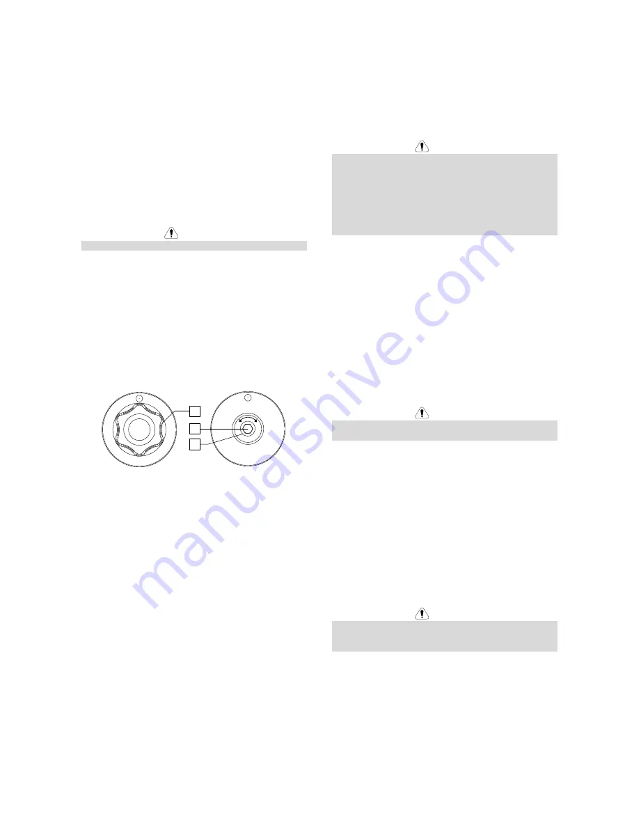
Adjustments of Brake Torque of Sleeve 

To avoid spontaneous unrolling of the welding wire the 
sleeve is fitted with a brake. 
Adjustment is carried by rotation of its screw M10, which 
is placed inside of the sleeve frame after unscrewing the 
locking nut of the sleeve. 

35

51

52


Figure 27. 

 
35. Locking Nut. 
51. Adjusting Screw M10. 
52. Pressing Spring. 
 
Turning the screw M10 clockwise increases the spring 
tension and you can increase the brake torque 
 
Turning the screw M10 anticlockwise decreases the 
spring tension and you can decrease the brake torque. 
 
After finishing of adjustment, you should screw in the 
locking nut again. 

Adjusting Pressure Roll Force 

The pressure arm controls the amount of force the drive 
rolls exert on the wire. 
Pressure force is adjusted by turning the adjustment nut 
clockwise to increase force, counterclockwise to 
decrease force. Proper adjustment of pressure arm 
gives the best welding performance. 
 

 WARNING


If the roll pressure is too low the roll will slide on the wire. 
If the roll pressure is set too high the wire may be 
deformed, which will cause feeding problems in the 
welding gun. The pressure force should be set properly. 
Decrease the pressure force slowly until the wire just 
begins to slide on the drive roll and then increase the 
force slightly by turning of the adjustment nut by one 
turn. 


Inserting Electrode Wire into Welding 
Gun 


Turn the input power OFF. 


Depending on welding process, connect the proper 
gun to the Euro Socket, the rated parameters of the 
gun and of the welding machine should be matched. 


Remote the nozzle from the gun and contact tip or 
protection cap and contact tip. Next, straighten the 
gun out flat. 


Insert the wire through the guide tube, over the roller 
and through the guide tube of Euro Socket into liner 
of gun. The wire can be pushed into the liner 
manually for a few centimetres, and should feed 
easily and without any force. 


 WARNING


If force is required it is likely that the wire has missed the 
liner of gun. 


Turn the input power ON. 


Depress the gun trigger to feed the wire through the 
gun liner until the wire comes out of the threaded 
end. Or the Cold Inch / Gas Purge Switch [12] can be 
used – keep in "Cold Inch" position until the wire 
comes out of the threaded end. 


When trigger or the Cold Inch / Gas Purge Switch 
[13] is released spool of wire should not unwind. 


Adjust wire spool brake accordingly. 


Turn the welding machine off. 


Install a proper contact tip. 


Depending on the welding process and the type of 
the gun, install the nozzle (GMAW process, FCAW-
GS process) or protection cap (FCAW-SS process). 


 WARNING


Take precaution to keep eyes and hands away from the 
end of the gun while the wire is being come out of the 
threated end. 

Summary of Contents for PF41

Page 1: ...IM3072 08 2017 REV01 PF41 OPERATOR S MANUAL ENGLISH Lincoln Electric Bester Sp z o o ul Jana III Sobieskiego 19A 58 263 Bielawa Poland www lincolnelectric eu ...

Page 2: ...feeder PF41 conforms to the following directives 2014 35 EU 2014 30 EU and has been designed in compliance with the following standards EN 60974 5 2013 EN 60974 10 2014 29 05 2017 Piotr Spytek Operations Director Lincoln Electric Bester Sp z o o ul Jana III Sobieskiego 19A 58 263 Bielawa Poland 07 11 ...

Page 3: ...in the table below your equipment identification information Model Name Code Serial Number can be found on the machine rating plate Model Name Code Serial number Date Where Purchased ENGLISH INDEX Technical Specifications 1 Electromagnetic Compatibility EMC 2 Safety 3 Introduction 4 Installation and Operator Instructions 4 WEEE 18 Spare Parts 18 Authorized Service Shops Location 18 Electrical Sche...

Page 4: ...ng Current Range Peak Open Circuit Voltage 5 500A 113Vdc or Vac peak DIMENSION Weight Height Width Length 18 kg 460 mm 300 mm 640 mm WIRE FEED SPEED RANGE WIRE DIAMETER WFS Range Drive Rolls Drive roll diameter Solid Wires Aluminum Wires Cored Wires 1 22 m min 4 Ø37 0 8 1 6 mm 1 0 1 6 mm 0 9 1 6 mm Protection Rating Maximum Gas Pressure Operating Temperature Storage Temperature IP23 0 5MPa 5 bar f...

Page 5: ...asurement Personal medical devices like pacemakers and hearing aids Check the electromagnetic immunity for equipment operating in or near the work area The operator must be sure that all equipment in the area is compatible This may require additional protection measures The dimensions of the work area to consider will depend on the construction of the area and other activities that are taking plac...

Page 6: ...tor creates electric and magnetic fields EMF EMF fields may interfere with some pacemakers and welders having a pacemaker shall consult their physician before operating this equipment CE COMPLIANCE This equipment complies with the European Community Directives ARTIFICIAL OPTICAL RADIATION According with the requirements in 2006 25 EC Directive and EN 12198 Standard the equipment is a category 2 It...

Page 7: ... of the machine Location and Environment This machine will operate in harsh environments However it is important that simple preventative measures are followed to assure long life and reliable operation Do not place or operate this machine on a surface with an incline greater than 15 from horizontal Do not use this machine for pipe thawing This machine must be located where there is free circulati...

Page 8: ... Connector Connection for gas line WARNING The welding machine supports all suitable shielding gases at a maximum pressure of 5 0 bar 7 Control Receptacle 5 pins receptacle for wire feeder connection To communication wire feeder with power source is used ArcLink protocol 8 Current Socket Input power connection 9 Quick Connect Coupling Coolant outlet takes warm coolant from welding machines to cool...

Page 9: ...again 4 step mode facilitates to making long welds The functionality of 2T 4T mode is shown in the Figure 4 Figure 4 Note 4 Step does not work during Spot Welding 14 Wire Spool Support Maximum 15kg spools Accepts plastic steel and fiber spools onto 51mm spindle Also accepts Readi Reel type spools onto included spindle adapter WARNING Be sure that wire spool case has to be completely closed during ...

Page 10: ...ng welding parameters Pinch Burnback Time Run in WFS Crater 28 Left Control Adjusts values on the left display 29 LED Indicator Informs that the value on the left display is in ampere units 30 LED Indicator Informs that the wire feed speed is on the left display Table 1 LED Light Condition Meaning Only machines which using ArcLink protocol for communication Steady Green System OK Power source is o...

Page 11: ...ss the Button 27 to confirm the settings LED Indicator 24 goes out Run in sets the wire feed speed from the time the trigger is pulled until an arc is established Factory default Run in is turned off Adjust range from minimum to maximum WFS To set Run in value Press the Button 27 until the LED indicator 25 will light up The Right Display blinks and shows Run in value Use The Right Control 22 to se...

Page 12: ...diting Confirm Parameter Value change 28 Parameter Selection The Setting and Configuration Menu includes the parameters described in Table 4 Table 4 The default settings of Menu The Menu Exit enables exit from menu Note This parameter cannot be edited To exit from menu In Advanced Menu select P000 Confirm the selection push the right button Wire Feed Speed WFS units enables change WFS units CE fac...

Page 13: ...t If the value is set to OFF machine output will not be turned off if an arc is not established nor will output be turned off if an arc is lost The trigger can be used to hot feed the wire default If a value is set the machine output will shut off if an arc is not established within the specified amount of time after the trigger is pulled or if the trigger remains pulled after an arc is lost To pr...

Page 14: ...firm the selection push the right button The blinking UI inscription appears on the left display and on the right the software version Note P103 is a diagnostic parameter to read only Welding Process Change it is possible to quick recall one of the non synergic welding programs 3 programs can be available Pr 5 GMAW Standard CV factory default Pr 6 FCAW SS Standard CV Pr 7 or 155 FCAW GS Standard C...

Page 15: ...ait until the PF41 will not be ready to work with the power source Status LED 18 stops blinking and lights steady green light Insert the wire into the welding gun WARNING Keep the gun cable as straight as possible when loading electrode through cable WARNING Never use defected gun Check gas flow with Gas Purge Switch 12 GMAW and FCAW GS process Close the wire drive door Close the spool wire case S...

Page 16: ...ate in a direction when feeding so as to be de reeled from bottom of the spool Re install the locking nut 35 Make sure that the locking nut is tightened Wire Spool Type S200 Loading WARNING Turn the input power OFF at the welding power source before installation or changing a wire spool Figure 22 Turn the input power OFF Open the spool wire case Unscrew the Locking Nut 35 and remove it from the Sp...

Page 17: ...l type B300 so that it will rotate in a direction when feeding so as to be de reeled from bottom of the spool Figure 25 Wire Spool Type Readi Reel Loading WARNING Turn the input power OFF at the welding power source before installation or changing a wire spool Figure 26 Turn the input power OFF Open the spool wire case Unscrew the Locking Nut 35 and remove it from the Spindle 37 Place the adapter ...

Page 18: ...djustment of pressure arm gives the best welding performance WARNING If the roll pressure is too low the roll will slide on the wire If the roll pressure is set too high the wire may be deformed which will cause feeding problems in the welding gun The pressure force should be set properly Decrease the pressure force slowly until the wire just begins to slide on the drive roll and then increase the...

Page 19: ... CYLINDER may explode if damaged Always fix the gas cylinder securely in an upright position against a cylinder wall rack or purpose made cylinder cart Keep cylinder away from areas where it may be damaged heated or electrical circuits to prevent possible explosion or fire Keep cylinder away from welding or other live electrical circuits Never lift welder with cylinder attached Never allow welding...

Page 20: ...ed from the machine before each maintenance and service After each repair perform proper tests to ensure safety Customer Assistance Policy The business of The Lincoln Electric Company is manufacturing and selling high quality welding equipment consumables and cutting equipment Our challenge is to meet the needs of our customers and to exceed their expectations On occasion purchasers may ask Lincol...

Page 21: ...er is not listed Contact the Lincoln Electric Service Department for any code number not listed Use the illustration of assembly page and the table below to determine where the part is located for your particular code machine Use only the parts marked X in the column under the heading number called for in the assembly page indicate a change in this printing First read the Part List reading instruc...

Page 22: ...ilable in 5 10 or 15m Speedtec Power Wave S350 S500 CE K10349 PGW xxM Source wire feeder cable gas and water Available in 5 10 or 15m Speedtec Power Wave S350 S500 CE K10348 PG xxM Source wire feeder cable gas Available in 5 10 or 15m Power Wave 455M Power Wave 455M STT Power Wave 405M K10348 PGW xxM Source wire feeder cable gas and water Available in 5 10 or 15m Power Wave 455M Power Wave 455M ST...

Page 23: ...English English 20 Connection Diagram ...

Page 24: ...English English 21 ...

Page 25: ...English English 22 ...

Reviews: