background image

INSTALLATION   

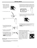
2. Attach the control cable

Amphenol, gas line con-
nector, and electrode
cable terminal to their
respective connectors
on the rear panel of the
Control Module.

3. At the other end of the cable:

Connect the gas line to the gas cylinder
regulator

4. Connect the Twist-Mate™ plug on

the electrode cable to the positive
(+) polarity mating plug on the
power source.

5. Connect the 14-pin Amphenol

connector to the mating con-
nector on the power source.

6. Set the Mode Switch on back of

the Control Module for the type
of contactor circuit in the power
source being used. See “Setting
the Mode Switch on Rear Panel”.
WARNING: Improper switch position
may result in equipment damage.

-13-

Installation of K691-10 Input Cable to Power Sources with a
14-pin Connector

1. Identify the cable end which has a 115V cordset with plug

attached to the Amphenol connector. This end attaches to
the engine-driven power source.

2. Connect the gas line to the gas cylinder regulator, connect

the electrode cable to the positive (+) output stud on the
power source, connect the control cable to the 14-pin
Amphenol connector on the power source (if present), and
plug the 115V plug into the outlet for 115V auxilliary power.

3. At the other end of the cable, attach the control cable

Amphenol connector, gas line connector, and electrode
cable terminal to their respective connectors on the rear
panel of the control module.

4. Set the Mode Switch on back of the Control Module for the

type of contactor circuit in the power source being used.
See “Setting the Mode Switch on Rear Panel”.
WARNING: Improper switch position may result in equip-
ment damage.

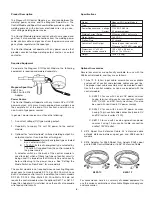
Setting the Mode Switch on Rear Panel

The slide switch on the rear panel selects between power
sources whose output contactors
are either internally energized or
externally energized from 115 VAC.
The Control Module is shipped
with the mode switch in the left
switch position and is for power
sources requiring only circuit clo-
sure (i.e., continuity) to energize
the output contactor. Lincoln ma-
chines are of this type. Right switch
position is for power sources re-
quiring that 115 VAC be supplied to
the contactor. 

Make appropriate

power source 

connections

and

Summary of Contents for MAGNUM SG CONTROL MODULE

Page 1: ...ALL OPERATE OR REPAIR THIS EQUIPMENT WITHOUT READING THIS MANUAL AND THE SAFETY PRECAUTIONS CONTAINED THROUGHOUT And most importantly think before you act and be careful For use with machines having Code Numbers Sales and Service through Subsidiaries and Distributors Worldwide Cleveland Ohio 44117 1199 U S A TEL 216 481 8100 FAX 216 486 1751 WEB SITE www lincolnelectric com World s Leader in Weldi...

Page 2: ...EARERS SHOULD CONSULT WITH THEIR DOCTOR BEFORE OPERATING Read and understand the following safety highlights For additional safety information it is strongly recommended that you purchase a copy of Safety in Welding Cutting ANSI Standard Z49 1 from the American Welding Society P O Box 351040 Miami Florida 33135 or CSA Standard W117 2 1974 A Free copy of Arc Welding Safety booklet E205 is available...

Page 3: ...l earth ground 3 f Maintain the electrode holder work clamp welding cable and welding machine in good safe operating condition Replace damaged insulation 3 g Never dip the electrode in water for cooling 3 h Never simultaneously touch electrically hot parts of electrode holders connected to two welders because voltage between the two can be the total of the open circuit voltage of both welders 3 i ...

Page 4: ... the welding sparks from starting a fire Remember that welding sparks and hot materials from welding can easily go through small cracks and openings to adjacent areas Avoid welding near hydraulic lines Have a fire extinguisher readily available 6 b Where compressed gases are to be used at the job site special precautions should be used to prevent hazardous situations Refer to Safety in Welding and...

Page 5: ... non inflammables 4 Des gouttes de laitier en fusion sont émises de l arc de soudage Se protéger avec des vêtements de protection libres de l huile tels que les gants en cuir chemise épaisse pan talons sans revers et chaussures montantes 5 Toujours porter des lunettes de sécurité dans la zone de soudage Utiliser des lunettes avec écrans lateraux dans les zones où l on pique le laitier 6 Eloigner l...

Page 6: ...the information must be followed to avoid minor personal injury or damage to this equipment CAUTION Please Examine Carton and Equipment For Damage Immediately When this equipment is shipped title passes to the purchaser upon receipt by the carrier Consequently Claims for material damaged in shipment must be made by the purchaser against the transportation company at the time the shipment is receiv...

Page 7: ...llation of K691 10 Input Cable with14 Pin Connector to 115V Plug 13 Setting the Mode Switch on Rear Panel 13 Connection to Spool Gun 14 Work Lead Connection 13 OPERATING INSTRUCTIONS 15 Safety Precautions 15 Initial Checkout of Magnum SG System Installation 15 Setting Gas Flow Rate on Gas Cylinder Regulator 16 Setting Gas Preflow Time on Control Module 16 Setting the Wire Speed 16 Setting Wire Spe...

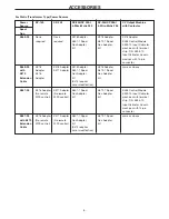
Page 8: ...rces having 14 pin control cable connection Lincoln CV and CV I series Invertec V 200 C K691 10 for use with Lincoln engine driven power sources having 14 pin control cable connection and or 115VAC outlet 2 K473 Spool Gun Extension Cable 25 extension cable extends distance between spool gun and K488 control module 3 K518 Adapter for K469 Spool Gun Adapts K469 spool gun to K488 Control Module or to...

Page 9: ...ter K518 Adapter K518 Adapter same as above with Adapter K517 Adapter K607 1 Spool K672 1 Spool K473 K516 Gun Adapter Gun Adapter Extension Adapter Kit Kit Cable K473 requires minor modification K487 25 K516 Adapter K517 Adapter K607 1 Spool K672 1 Spool K488 Control Module No remote No remote Gun Adapter Gun Adapter K492 10 Input Cable for WFS control WFS control Kit Kit machines with terminal st...

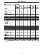
Page 10: ...10 N Ranger 300DLX Y N Y Y K691 10 Y Ranger 8 Incl CSA LPG N N N Y K691 10 N Ranger 9 Incl CSA Y N Y Y K691 10 Y SA 250 N N N Y K691 10 N SA 250 w CV Adapter N N N Y K691 10 N SA 250 w Wire Feed Module Y N Y Y K691 10 Y 350 SA N N N Y K691 10 N 350 SA w Wire Feed Module Y N Y Y K691 10 Y SAE 350 w CV Adapter N N N Y K691 10 N SAE 400 w CV Adapter N N N Y K691 10 N SAE 400 WELD N AIR w CV Adapter N...

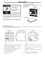
Page 11: ...strations and numbered items below for brief description 1 Wire speed control potentiometer for varying wire feed speed 2 Preflow timer 0 1 second adjusts wire feeder start up delay time from when gas flow starts 3 2A circuit breaker manual reset protects control circuitry 4 Output connector for spool gun electrode cable 5 Connector for spool gun control cable 6 Gas fitting for spool gun gas line ...

Page 12: ... access panel for the terminal strip on the power source and connect the control cable a Connect the terminal on the green lead marked GND to the ground screw on the chassis panel or terminal strip b Connect the white and black lead terminals marked 31 and 32 to the corresponding 115 VAC terminals on the terminal strip c Connect the remaining two leads marked 2 and 4 to the corresponding terminals...

Page 13: ... to the positive output stud on the power source connect the control cable to the 14 pin Amphenol connector on the power source if present and plug the 115V plug into the outlet for 115V auxilliary power 3 At the other end of the cable attach the control cable Amphenol connector gas line connector and electrode cable terminal to their respective connectors on the rear panel of the control module 4...

Page 14: ...ool Gun 1 Connect K518 adapter to spool gun control cable 2 Connect the electrode cable gas line and control cable of the spool gun to their respective connectors on the front of the Control Module Requires K518 adapter ordered separately CAUTION Be sure that mode switch is in correct position before attempting to operate control module Incorrect switch position could result in damage to the contr...

Page 15: ...urce 7 Pick up spool gun and squeeze spool gun trigger Solenoid valve in Control Module should energize Gas should be heard flowing from cone of spool gun Drive roll in spool gun should rotate clockwise 8 Rotate wire speed control knob on Module from minimum to maximum with trigger pressed and verify that drive roll speed increases significantly 9 For K847 spool gun only rotate speed control in ha...

Page 16: ...e wire speed control knob on the Control Module to maximum The control in the handle of the spool gun now varies the wire speed across the entire range approximately 50 to 650 ipm 1 3 to 16 5m min In general the spool gun potentiometer varies the speed between 0 and 100 of the Control Module wire speed control setting A good practice is to set the Control Module speed potentiometer for the maximum...

Page 17: ...or all machines covered by this manual The specific diagram for a particular code is pasted inside the machine on one of the enclosure panels If the diagram is illegible write to the Service Department for a replacement Give the welder code number 12 89 17 Wiring Diagram ...

Page 18: ...NOTES ...

Page 19: ...16 383 2259 and ask for the Welding School Registrar Lincoln Welding School BASIC COURSE 700 00 5 weeks of fundamentals There is a 10 discount on all orders of 50 00 or more for shipment at one time to one location Orders of 50 or less before discount or orders outside of North America must be prepaid with charge check or money order in U S Funds Only Prices include shipment by 4thClass Book Rate ...

Page 20: ...electrically live parts or electrode with skin or wet clothing Insulate yourself from work and ground No toque las partes o los electrodos bajo carga con la piel o ropa moja da Aislese del trabajo y de la tierra Ne laissez ni la peau ni des vête ments mouillés entrer en contact avec des pièces sous tension Isolez vous du travail et de la terre Berühren Sie keine stromführenden Teile oder Elektrode...

Page 21: ...gute Be und Entlüftung des Arbeitsplatzes Mantenha seu rosto da fumaça Use ventilação e exhaustão para remover fumo da zona respiratória Turn power off before servicing Desconectar el cable de ali mentación de poder de la máquina antes de iniciar cualquier servicio Débranchez le courant avant l entre tien Strom vor Wartungsarbeiten abschalten Netzstrom völlig öff nen Maschine anhalten Não opere co...

Page 22: ...s and Service through Subsidiaries and Distributors Worldwide Cleveland Ohio 44117 1199 U S A TEL 216 481 8100 FAX 216 486 1751 WEB SITE www lincolnelectric com World s Leader in Welding and Cutting Products ...

Reviews: