Lincoln Electric INVERTEC 275TP Operator'S Manual Download Page 14

English 12 English 


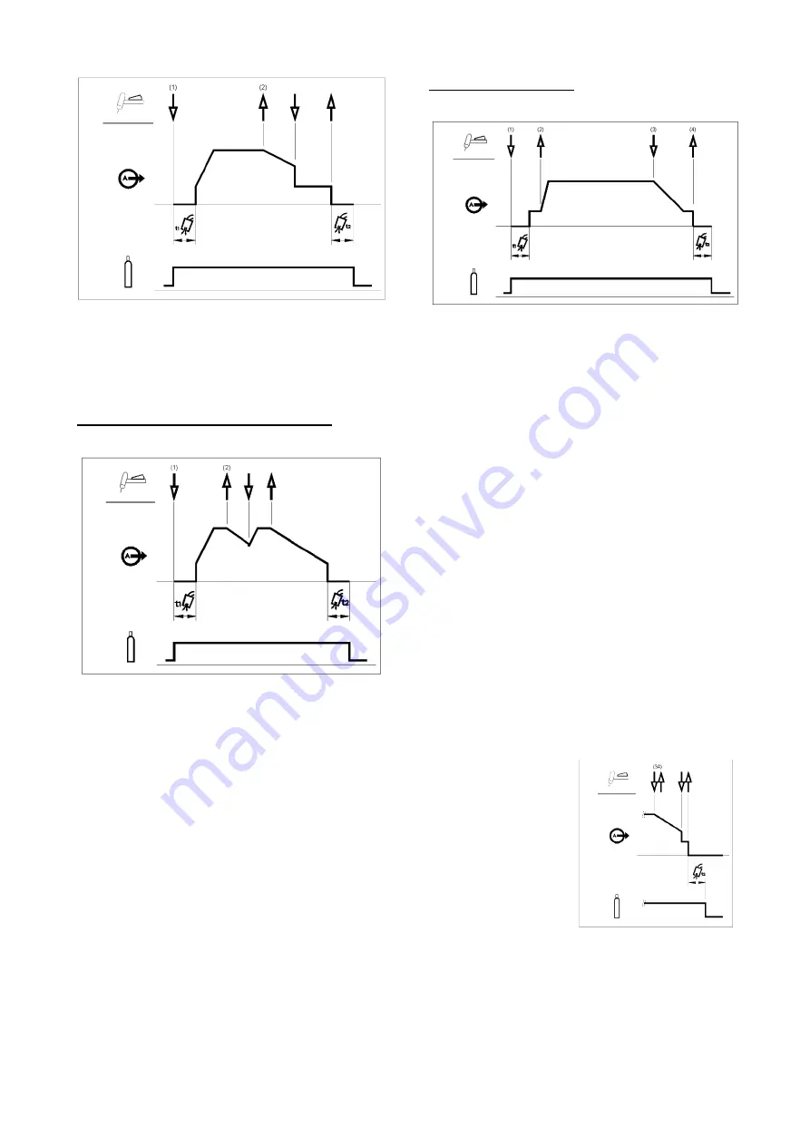
As shown above, it is possible to press and hold the TIG 
torch trigger a second time during downslope to end the 
downslope function and maintain the output current at 
the Crater current.  When the TIG torch trigger is 
released the output will turn OFF and the post flow time 
will start.  This operation sequence, 2-step with restart 
disabled, is the default setting from the factory. 
 

2-Step Trigger Sequence with Restart Option 

If the 2-step restart option is enabled from the setup 
menu the following sequence will occur: 


1.  Press and hold the TIG torch trigger to start the 

sequence as described above. 

2. Release the TIG torch trigger to start the 

downslope.  During this time press and hold the TIG 
torch trigger to restart welding.  The output current 
will increase again at a controlled rate until the 
Welding current is reached.  This sequence can be 
repeated as many times as necessary. When the 
welding is complete release the TIG torch trigger. 
When the Crater current is reached the output of the 
machine is turned OFF. 


4-Step Trigger Sequence 

With the 4-step trigger mode and a TIG welding mode 
selected, the following welding sequence will occur. 


1.  Press and hold the TIG torch trigger to start the 

sequence.  The machine will open the gas valve to 
start the flow of the shielding gas.  After the pre-flow 
time, to purge air from the torch hose, the output of 
the machine is turned ON. At this time the arc is 
started according to the selected welding mode.  
After the arc is started the output current will be at 
the Start current. This condition can be maintained 
as long as necessary. 


If the Start current is not necessary, do not hold the 
TIG torch trigger as described at the beginning of this 
step.  In this condition, the machine will pass from 
Step 1 to Step 2 when the arc is started. 

 
2. Releasing the TIG torch trigger starts the upslope 

function. The output current will be increased at a 
controlled rate, or upslope time, until the Welding 
current is reached. If the torch trigger is pushed 
during the upslope time the arc will stop immediately 
and the output of the machine is turned OFF.  

 
3.  Press and hold the TIG torch trigger when the main 

part of the weld is complete.  The machine will now 
decrease the output current at a controlled rate, or 
downslope time, until the Crater current is reached. 

 
4.  This Crater current can be maintained as long as 

necessary. When the TIG torch trigger is released 
the output of the machine is turned OFF and the 
post flow time will start. 

 
As shown here, after the 
TIG torch trigger is quickly 
pressed and released 
from step 3A, it is possible 
to press and hold the TIG 
torch trigger another time 
to end the downslope time 
and maintain the output 
current at the Crater 
current.  When the TIG 
torch trigger is released 
the output will turn OFF. 
 
This sequence operation, 4-step with restart disabled, is 
the default setting from the factory. 
 

Summary of Contents for INVERTEC 275TP

Page 1: ...IM3136 09 2021 REV02 INVERTEC 275TP OPERATOR S MANUAL ENGLISH Lincoln Electric Bester Sp z o o ul Jana III Sobieskiego 19A 58 260 Bielawa Poland www lincolnelectric eu...

Page 2: ...enter your product identification data in the table below Model Name Code Serial Number can be found on the machine rating plate Model Name Code Serial number Date Where Purchased INDEX Technical Spec...

Page 3: ...0 180A 60 230A 35 250A OUTPUT RANGE Welding Current Range Peak Open Circuit Voltage U0 GTAW 5 270A 72V SMAW 5 250A DIMENSIONS AND WEIGHT Weight Height Width Length INVERTEC 275TP 16 kg 360 mm 230 mm 4...

Page 4: ...de X STICK mode After 30 minutes of non working X Fan off X The value of efficiency and consumption in idle state have been measured by method and conditions defined in the product standard EN 60974 1...

Page 5: ...into the welding pool Notice A cross wind or draft moving can disrupt the shielding gas coverage in the interest of saving of protective gas use screen to block air flow End of life At end of life of...

Page 6: ...or adjacent to the work area and the machine Radio and or television transmitters and receivers Computers or computer controlled equipment Safety and control equipment for industrial processes Equipme...

Page 7: ...cordance with local electrical regulations ELECTRICALLY POWERED EQUIPMENT Regularly inspect the input electrode and work clamp cables If any insulation damage exists replace the cable immediately Do n...

Page 8: ...to a fixed support Do not move or transport gas cylinders with the protection cap removed Do not allow the electrode electrode holder work clamp or any other electrically live part to touch a gas cyl...

Page 9: ...er than 40 C Duty cycle and Overheating The duty cycle of a welding machine is the percentage of time in a 10 minute cycle at which the welder can operate the machine at rated welding current Example...

Page 10: ...ecting a Remote Control Kit 6 User Interface See User Interface section 7 USB connector Back panel INVERTEC 275TP Figure 2 1 Gas quick coupling socket For connecting a gas pipe 2 Power switch WARNING...

Page 11: ...Soft Crisp etc If Guided Setup Mode is selected all inputs will be displayed in the section 2 Status Bar give additional information like Trigger Interlock selection remote control status 3 Preset Cur...

Page 12: ...dicated Section Configure Parameters Arc Strike Figure 7 To select the type of arc striking HF or Touch Start select the corresponding menu and push the Knob Figure 8 Select the arc strike type desire...

Page 13: ...trigger mode and a TIG welding mode selected the following welding sequence will occur 1 Press and hold the TIG torch trigger to start the sequence The machine will open the gas valve to start the fl...

Page 14: ...rom the torch hose the output of the machine is turned ON At this time the arc is started according to the selected welding mode After the arc is started the output current will be at the Start curren...

Page 15: ...the main part of the weld is complete go to step 3 As shown here again after the TIG torch trigger is quickly pressed and released from step 3A it is possible to quickly press and release the TIG torc...

Page 16: ...a new icon will be present for time configuration Tack For Thin sequence Tack for Thin sequence is very identical to Spot sequence but ramp up and ramp down phases of weld sequence are not present Cur...

Page 17: ...e 16 The machine allow the user the use 4 stick mode Soft For a welding with a low spatter presence Hot Start and Arc Force are pre defined and can not be modified Crisp For an aggressive welding with...

Page 18: ...ddle that occur during normal stick welding Figure 18 Anti Sticking This feature cannot be modified by user This is a function that decreases the output current of the machine to a low level when the...

Page 19: ...GTAW and SMAW Potentiometer torch has the same behavior than Foot Pedal Amperage UP DOWN Torch Usable in GTAW only Three operating modes corresponding to different states of the machine are identifie...

Page 20: ...ng to be saved are displayed 2 With the knob it is possible to scroll up or down to select an empty or used slot memory If the slot is already used the parameters associated to the backup are displaye...

Page 21: ...ll be adjusted by Adding list of all inputs data in Primary Settings section Preset a defined current value Modifying current range ribbon Primary settings To change and configure input parameters pre...

Page 22: ...Vrd can be activated deactivated Configuration of Cooler System Information The software revision will be displayed in this section Software upgrade Software will be released during the life time of...

Page 23: ...and lifting with a crane adhere to the following rules The device contains elements adapted for transport For lifting a suitable lifting equipment capacity WARNING In any way the power source cannot b...

Page 24: ...or any customer s particular purpose with respect to such information or advice As a matter of practical consideration we also cannot assume any responsibility for updating or correcting any such info...

Page 25: ...uding removal of accumulated dust and dirt from the intake and outlet louvers User interface show information when machine will be cooled down To continue welding operation Please press left knob or s...

Page 26: ...First read the Part List reading instructions above then refer to the Spare Part manual supplied with the machine that contains a picture descriptive part number cross reference REACh 11 19 Communicat...

Page 27: ...79 W000278922 WTT2 9 EB W000278875 WTT2 17 RL W000278884 W000278917 WTT2 17 EB W000278882 W000278919 WTT2 26 RL W000278890 W000278913 WTT2 26 EB W000278887 W000278915 TIG TORCHES WATER 4mt 8mt WTT2 18...

Reviews: