4
LINCE ITALIA S.p.A.
2. COLLEGAMENTI ELETTRICI ED
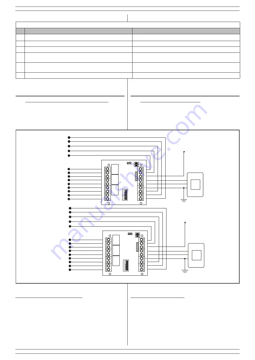
ESEMPIO DI COLLEGAMENTO
Al fine di effettuare opportunamente e agevolmente i collegamenti
elettrici, collegare alimentazione, massa e dati tra la scheda inseritore
e la scheda interfaccia rispettando le serigrafie riportate su entrambe le
schede. Collegare quindi i morsetti ingresso/uscita ai relativi dispositivi
esterni.
Fig. 2
C3 NC3 NA3 C2 NC2 NA2 C1 NC1 NA1
S F BUS D + 12V LM OFF
ON
S
: uscita OC
F
: uscita OC
BUS:
Uscita stato
LM
: Ingresso linea aperta
OFF:
uscita
Alimentazione
Scambi relè modalità
Impulsiva o passo passo
in funzione dei dip-switch
4, 5, 6.
{
Inseritore su BUS
Tabella 4 - Table 4
DIP
OFF (Default)
ON
6
Relè n° 1 bistabile /
Relay n° 1 bistable
Relè n° 1 Impulsivo (1 s) /
Relay n° 1 pulse
5
Relè n° 2 bistabile /
Relay n° 2 bistable
Relè n° 2 Impulsivo (1 s) /
Relay n° 2 pulse
4
Relè n° 3 bistabile /
Relay n° 3 bistable
Relè n° 3 Impulsivo (1 s) /
Relay n° 3 pulse
3
LED stato relè attivi con tag presente
Active relay status LED with present tag
LED stato relè spenti con tag non presente
Relay LED status off with tag not present
2
Modo di funzionamento a tre relè (tag completo)
Three relay operating mode (full tag)
Modo di funzionamento ad un solo relè
Single relay operating mode
1
Acquisizione non abilitata /
Memorization not enabled
Acquisizione abilitata /
Memorization enabled
1.4 DESCRIZIONE DEI DIP-SWITCH
2. ELECTRICAL CONNECTIONS AND
EXAMPLE OF WIRING
In order to make the electrical connections properly and easily, connect
the power supply, ground and data between the key reader board and the
interface board, respecting the silk-screen printed on both boards. Then
connect the input / output terminals to the relevant external devices.
C3 NC3 NA3 C2 NC2 NA2 C1 NC1 NA1
S F BUS D + 12V LM OFF
ON
Power supply
Key reader on bus
S
: OC output
F
: OC output
BUS:
status output
LM
: open line input
OFF:
output
Relay otuputs
pulse or latching according
to the dip-switches 4 , 5, 6.
{
3.1 RESET INIZIALE
A scheda disalimentata, premere e mantenere premuti entrambe i tastini
( ACQ e PRG ) e successivamente alimentare la scheda. Dopo l’avvio
della sequenza di lampeggi ed accensione dei due LED, rilasciare i
tastini.
3. PROGRAMMAZIONE
3. PROGRAMMING
3.1 FIRST RESET
With the board disconnected, press and hold both buttons (ACQ and
PRG) and then power on the board. After starting the flashing sequence
and turning on the two LEDs, release the buttons.
1.4 DIP-SWITCHES DESCRITPION
Massa (comune)
Ground (common)


