


Page 66 / 78
Section 8. Firmware upgrade
8. Firmware upgrade
Using Lightware bootloader application to upgrade router’s firmware
The matrix router can only be upgraded via LAN, so connect the matrix router to
the local subnet. Be sure that there is no other active connection with the router via
Ethernet.
Step 1.
Install the bootloader application with “Installer_LW_bootloader.exe”
Step 2.
Download and save all the firmware files that you want to load. If you have
a zipped archive, extract it.
Step 3.
Run the application from
Start Menu
Programs
Lightware
LW_bootloader.
Step 4.
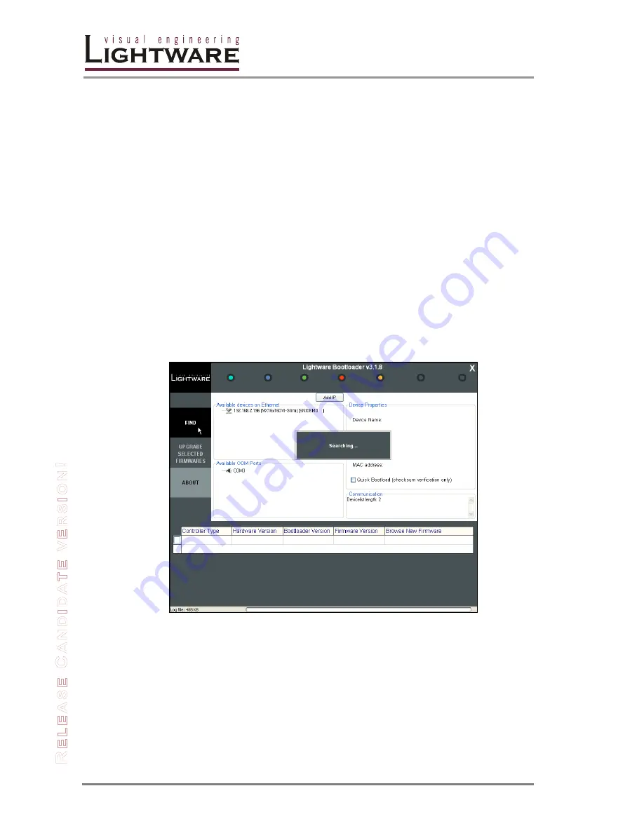
Click “
FIND
” Button!
If the bootloader finds one or more routers their IP addresses will be listed in the
tree view window. On the tree view, device type and serial number is shown after
the IP address.
Info
Note, that you must wait until all the devices on the network completely start up,
before pressing FIND button.
Figure 8-1. Bootloader searches for devices
Summary of Contents for MX12x12DVI-Slim
Page 1: ...User s Manual MX16x16DVI Slim MX12x12DVI Slim ...
Page 2: ...Page 2 78 ...


