Lightronics RD-121, Owner'S Manual
The Lightronics RD-121 Owner's Manual is available for free download on our website. This comprehensive manual provides easy-to-follow instructions for setting up and operating the RD-121, ensuring you get the most out of your product. Download your manual today from manualshive.com and unlock the full potential of your Lightronics RD-121.
Share
Download


Reviews:
No comments
Related manuals for RD-121

H1
Brand: NARGESA Pages: 33

X200
Brand: DARAY Pages: 28

3020
Brand: MacDon Pages: 88

56
Brand: Jiffy Pages: 15

CD-RW880
Brand: Teac Pages: 44

Racewell HD3
Brand: Te Pari Pages: 6

KC501
Brand: Xtool Pages: 8

1973
Brand: Keithley Pages: 57

Ti-Lite Carbo AirBlock 351
Brand: Harken Pages: 2

GMXB1020-2
Brand: Garten Meister Pages: 28

Pulsors
Brand: Albrecht Pages: 4

MICRO BEAMER RGBW
Brand: Briteq Pages: 16

Micro 3
Brand: Gerber Instruments Pages: 18

OSTANA
Brand: IKEA Pages: 16

Ruby Royal
Brand: American DJ Pages: 12

ACHILLES
Brand: aion Pages: 10

250-71
Brand: COOPS & FEATHERS Pages: 4
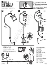
Malibu CM230
Brand: Intermatic Pages: 2


