Briteq MICRO BEAMER RGBW, Operation Manual
The Briteq MICRO BEAMER RGBW is a versatile lighting fixture that offers vivid color options. Enhance your lighting experience with this compact fixture that is perfect for small venues and events. To learn more about its features and settings, visit our website and download the free Operation Manual today.
Share
Download


Reviews:
No comments
Related manuals for MICRO BEAMER RGBW

700
Brand: B&K Pages: 5

1621
Brand: B&K Pages: 28

SC1
Brand: Raven Pages: 27

SC1
Brand: Raven Pages: 79

SC1
Brand: Raven Pages: 88

US-1200
Brand: Tascam Pages: 8

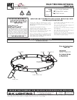
Union Bollard
Brand: B-K lighting Pages: 5

RE1
Brand: B-K lighting Pages: 4

PS
Brand: B-K lighting Pages: 3

UL Series
Brand: B-K lighting Pages: 4

Precision2 HP2 Series
Brand: B-K lighting Pages: 3
ArtiStar Series
Brand: B-K lighting Pages: 3
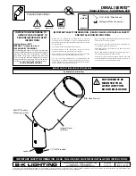
Denali Series
Brand: B-K lighting Pages: 3
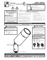
Denali Series
Brand: B-K lighting Pages: 38

TX31
Brand: IBEX Pages: 4

MS 3
Brand: Mach Pages: 12

VLR100 LED Series
Brand: WE-EF Pages: 3

ENCELIUM
Brand: Osram Pages: 4


