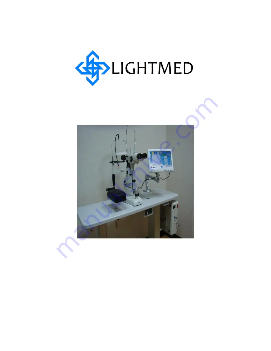
Operator Manual
Multi-Wavelength Pattern
Scanning System – LightLas
532 / 670
Page 1: ...Operator Manual Multi Wavelength Pattern Scanning System LightLas 532 670 ...
Page 2: ... Scanning System LightLas 532 670 Operators Manual Rev No 01 Page 1 of 126 Operator Manual for the Multi Wavelength Pattern Scanning System LightLas 532 670 Directive 93 42 EEC as amended by 2007 47 EC Doc No DC1800 Rev No 01 ...
Page 3: ... in hazardous radiation exposure CAUTIONS Any modification to the Ophthalmic Laser will result in the necessity for it to be reclassified CAUTIONS U S law restricts this device to sale by or on the order of a physician This Service Manual contains confidential and proprietary information of the Manufacturer Manufactured by LightMed Corporation No 1 1 Ln 1 Pao An St Sec 3 Shulin Dist New Taipei Cit...
Page 4: ...Multi Wavelength Pattern Scanning System LightLas 532 670 Operators Manual Rev No 01 Page 3 of 126 ...
Page 5: ...2 1 Laser Delivery Unit LDU 25 3 3 1 Accessories 26 3 2 CSO SL980 Slit lamp Specifications 26 Section 4 PRINCIPLES OF OPERATION 27 4 1 General Description 27 4 2 Laser Console 35 4 3 LCD Control Panel Display Screen 41 4 3 1 Console Control Screen 39 4 3 2 Pattern Control Screen 39 4 4 Remote Control Panel 53 4 5 Truscan Integrated into CSO model SL980 57 A Integrated CSO SL980 Controls Breakdown ...
Page 6: ...l V a l i d a t i o n O p t i o n a l 8 9 Section 6 CLINICAL USE 93 6 1 Different types of LDUs Indication Contraindication Use 94 6 1 1 Slit lamp Delivery Unit 94 6 1 2 Laser Indirect Ophthalmoscope LIO 94 6 1 3 Endoprobe devices 95 6 2 General Warnings 97 6 3 Possible side effect or adverse reactions 99 Section 7 MAINTENANCE 100 7 1 Operator User Maintenance 100 7 2 Laser Beam Alignment Check 10...
Page 7: ... Parts List and Controls 58 4 10 b SL980 Slit lamp Parts List and Controls 59 4 11 a Front View of LIO LDU Controls 60 4 11 b Top View of LIO LDU Controls 60 5 1 Integrated Slit lamp LDU Packing 65 5 2 Portable Carry Cases for Console and LDU s 65 5 3 Inter power Connection Left hand side 69 5 4 Slit lamp with Power Plugs Facing Each Other 69 5 5 a Rear View Box Connection 70 5 5 b Removal Fuse So...
Page 8: ...81 5 16 b System Ready to operate 81 5 17 a Fiber and Delivery Key fitted to Console Front Panel 83 5 17 b Fiber tips cleaning 83 5 17 c LCD LIO Intensity Control Knob 84 5 17 d LIO Intensity Control Knob 84 5 18 Endoprobe plug installation 85 5 19 a Front End Connection 89 5 19 b Rear End Connection 89 5 20 a System boot up sequential display 1 90 5 20 b System boot up sequential display 2 90 5 2...
Page 9: ...532 670 The Manufacturer and Distribution organization shall not be held liable or responsible for damages or injury caused as a result of using non approved accessories This includes all Optical Fiber systems Laser Delivery Units Safety Filters Safety Glasses and Table units All maintenance and service work must be carried out by authorized and trained service agents and only those procedures out...
Page 10: ... a Class IV laser product as specified in the standard IEC60825 1 2007 and the USA 21 CFR s 1040 10 1040 11 The Multi Wavelength Pattern Scanning System LightLas 532 670 Photocoagulator Laser is classified as Class I Type B Electromedical equipment as specified in the IEC60601 1 standard The Multi Wavelength Pattern Scanning System LightLas 532 670 Photocoagulator Laser is classified as a Class II...
Page 11: ...Laser directly onto flammable agents or gasses as the focused laser beam may cause ignition There is no AP APG protection DO NOT try to service or repair the laser other than what is included in this manual Service should only be performed by an authorized and trained agent of the manufacturer DO NOT fire the laser on a patient without first checking the operation of the laser and verifying the op...
Page 12: ... 21CFR 1040 10 1040 11 and ANSI Z136 1 1986 During normal operation of the Multi Wavelength Pattern Scanning System LightLas 532 670 the operator is protected from Laser hazards by built in optical absorption Safety Filters All other personnel in the area should wear protective eyewear to eliminate the risk of eye injury occurring The optical density OD of eye protection must be greater than or eq...
Page 13: ...s to the equipment should be wearing eye protection Patients where possible should have the untreated eye covered or protected from laser reflections 2 3 2 Avoid Exposure to Laser beams Reassembly or maintenance of the laser system should only be performed by authorized and trained personnel The external housing of the laser system should never be removed otherwise you or standby observers could b...
Page 14: ...e with three terminal prongs AC voltage where the third prong pin is the earth grounded prong Warning It is not safe to operate the Multi Wavelength Pattern Scanning System LightLas 532 670 photocoagulator laser without an earth grounded receptacle There is possible risk of electric shock No cover or housing need to be removed by the operator or user Only the authorized and trained service or agen...
Page 15: ...ety Controls and Features For the Multi Wavelength Pattern Scanning System LightLas 532 670 to comply to the various requirements of the standards referred to previously there are a number of Controls and Features that are provided refer to Figure 2 1 Figure 2 1 Safety Controls and Features 1 2 4 3 8 7 5 6 9 ...
Page 16: ...les located in the laser source aperture that completely blocks the beam path at all times except when the system is in the READY mode and footswitch is activated There are electronic sensors that check the position of the shutter at all times for the microprocessor Whenever the system boots up it will check for the shutter position to validate if the shutter is engaged and functioned Another safe...
Page 17: ...ch contact is good It is not possible to go to the READY mode or change any set up condition if the footswitch is already depressed 9 Volume Control Bar This control bar is the beeping warning control It will give the operator a warning sound in regarding if there is an error or warning occurred and cannot be turned off When the Multi Wavelength Pattern Scanning System LightLas 532 670 is first tu...
Page 18: ...or no controls are operated for 10 minutes the System will go back to the STANDBY mode if it was set into the READY mode The Console gives an audible warning whenever the laser is firing Note With all these controls and features the Multi Wavelength Pattern Scanning System LightLas 532 670 is a very safe instrument when it is used correctly and as indicated in this manual ...
Page 19: ...isque de chocs electriques Laser direct ou diffuse reparations par service connect only to with a Hospital Complies to the requirements of 21CFR Chapter 1 Subchapter J Kundendienst FOOTSWITCH DOOR INTERLOCK JOYSTICK Dieses Gerat ist nicht fur den Betrieb in explosiongefahrdeten bereichen bestimmt EXPLOSIONSGEFAHR SCAN DELIVERY Danger Caution AVOID EYE OR SKIN EXPOSURE TO DIRECT OR SCATTERED RADIAT...
Page 20: ...s LIGHTLAS INSTRUCTIONS Table up down control is under table top Slit lamp illumination is located under the table top Indirect if using insert illumination plug into panel socket Switch On insert key serrated edge uppermost turn gently clockwise Intructions Model Serial Number New Taipei City 23861 TAIWAN R O C Pao An St Sec 3 Shulin Dist Manufactured By Manufactured LightMed Corporation No 1 1 L...
Page 21: ...ANGER CAUTION VISIBLE LASER RADIATION AVOID EYE OR SKIN EXPOSURE TO DIRECT OR SCATTERED RADIATION CLASS 4 IV LASER PRODUCT IEC60825 1 2007 SD3100 03 CAUTION DANGER AVOID EYE OR SKIN EXPOSURE TO DIRECT OR SCATTERED RADIATION Manufactured Lightmed Corporation OD4 532 670nm Safety Filter 0434 Serial No Model No Figure 2 4 a Integrated Slit lamp LDU with labels RH side ...
Page 22: ...Multi Wavelength Pattern Scanning System LightLas 532 670 Operators Manual Rev No 01 Page 21 of 126 2 62 Integrated Slit lamp LDU continues Figure 2 4 b Integrated Slit lamp LDU with labels LH side ...
Page 23: ...lobal Pty Ltd Safety Filter OD4 532nm Manufactured Lightmed Corporation Serial No Model No OD4 532nm 670nm Safety Filter DIRECT OR SCATTERED RADIATION AVOID EYE OR SKIN EXPOSURE TO DANGER CAUTION Visible when open 0434 Manufactured AVOID EYE OR SKIN EXPOSURE TO Visible laser radiation when open DIRECT OR SCATTERED RADIATION DANGER CAUTION Figure 2 5 LIO LDU with labels ...
Page 24: ... 30 C Storage 10 to 55 C Relative Humidity Range Operating 30 85 non condensing Storage and Transport up to 95 non condensing Atmospheric pressure Operating 800 1060 mbar Storage and Transport 500 1060 mbar Cooling System Fan cooled and TEC s for Laser Diode and Crystal Dimensions 130mm H x 370mm W x 330mm D Weight 13 Kg System 20 Kg Packed Treatment Laser Laser Type Diode Laser Diode Laser Wavele...
Page 25: ...splay accuracy Better than 20 of actual Beam Divergence 0 2 NA Aiming Laser Laser Type Red Laser Diode Wavelength 635 650 nm Red Mode of Operation CW Output power Maximum of 1 0mW Power Adjustment Continuously variable Safety Class Class 2 3 2 1 Laser Delivery Units Integrated Slitlamp LDU Slitlamp model CSO Model SL980 K992836 Spot Sizes 50 m 1000 m continuously selectable on Zoom assembly of Del...
Page 26: ...ting Fiber Length 3 m Safety Filters OD 4 in housing for installation to Operating Microscope before Laser can be fired Sterile Sterilized by Ethylene Oxide and packed as Single use devices ready for use Beam Divergence 0 2 NA 3 31 Accessories Safety filter Safety Filters OD 4 532 nm and 670nm Pattern Scanning Single Line Square 2x2 3x3 4x4 5x5 Macular Arc single double triple 1 4 1 2 3 4 Circle a...
Page 27: ... SL980 is a Zeiss clone and uses an illumination source below the viewing path Microscope Galilean Magnification Set 5 Step Drum Rotation Eyepiece 12 5X Magnification Ratio 6X 10X 16X 25X 40X PD Range 48 5 80mm Diopter Adjustment 8 Slit Illumination 6V 20W Halogen Lamp Slit Width 0 14mm Slit Length 1 8 12mm Slit Apertures 0 3 5 5 9 14mm Slit Angles 0 180 Filters Red Free Heat Absorbing Cobalt Blue...
Page 28: ...llimated which means that the beam does not diverge and can maintain a constant diameter over a long distance This means that the Laser beam can be focused to a very small spot with high energy and power densities The beam is Monochromatic which means that it is a single wavelength beam and therefore the effects of the beam on tissue are very predictable and reproducible The light waves are cohere...
Page 29: ...s recommended that always start with a lower power and shorter pulse interval to reduce any risk of unintended injury to the patient By default setting the laser system the power is set to 0mW the pulse duration is set to 0 02 seconds and the pulse interval is set to One which means one shot per requested only These settings can be altered and saved by the operators or doctors preference Conversel...
Page 30: ...Lens that is held by the doctor and assists in positioning the laser beam on the site and setting the desired spot size For the Slit lamp delivery unit the spot size at the treatment site is adjustable and set by the doctor according to the type of treatment to be used The spot size selector is located on the delivery unit attached to the Slit lamp and can be set from 50µm to 1000µm in a continuou...
Page 31: ...hs describe the actual operation of the system The system consists of two major parts the console and the LCD touch control panel integrated with computer platform Inside the Laser Console there are several operating components that put together to provide the output Laser beam such as Laser Diode 808nm and 635 650nm Cavity Module Optics system Thermal Electric Coolers and Driver units Electronic ...
Page 32: ...ng System LightLas 532 670 Operators Manual Rev No 01 Page 31 of 126 this manual This process usually takes less 5 mins Figure 4 1 System software start up screen shot Figure 4 2 System software boot up ok and system is Standby mode ...
Page 33: ...w enabled and the aiming beam is turned on If the footswitch is pressed the appropriate laser beam will be delivered into the fiber The system will turn back to STANDBY mode in the following situations No controls are operated for 10 minutes Any warning or error condition occurs Prior to activate the READY mode it is recommended that all operating conditions are to be set correctly such as patient...
Page 34: ... pressed the microprocessor will carry out various checks on the status of the laser system including the correct position of the shutter After the microprocessor finishes the system checking then the shutter will await to be opened or activated If this is OK then the Laser Diode will be turned on for the selected pulse duration There is a closed loop control system to ensure a stable output pulse...
Page 35: ...tion and control of the Multi Wavelength Pattern Scanning System LightLas 532 670 Laser Depending on the type of surgery being performed the delivery unit being used and the condition of the patient the doctor must decide on the modality of the Laser use and whether or not an assistant is required during the surgery As the laser system is designed to deliver the laser beam to heat the tissue care ...
Page 36: ...sole front panel or the rear panel and LCD display control panel refer to fig 4 4 4 7 A detailed description of each control and display is explained on the next page Figure 4 4 Laser Console Connection Controls Legend 1 Emergency Stop Switch 2 Key Switch 3 Laser Aperture 4 Delivery Key Connector 5 LIO Power 6 Main Power Inlet 7 Footswitch Connector 8 Remote Interlock Connector 9 Joystick Connecto...
Page 37: ...through this aperture unless the fiber is securely attached 4 Delivery Key Connector Each Delivery Unit has its own type of Delivery Key connector that must be fitted to this socket so the microprocessor can recognize it Always make sure the correct Delivery Key is inserted for the LDU that is being used 5 LIO Power This connector is used to supply the power to the LIO Illumination Whenever the LI...
Page 38: ...tem will go default back to STANDBY mode By default setting a dummy Interlock connector is supplied with each console and it must insert in order for the system to operate correctly 9 Joystick Connector This connector is used to feedback or monitor joystick movement during normal operation 10 Scan Delivery This connector will monitor and interface signal with Truscan spot size encoders and motor p...
Page 39: ...tem LightLas 532 670 system software features several type of screens as well as pop up windows that display on the screen The screen is divided into two major portions Left hand side of screen is called the pattern scanning screen and the right hand side is the console screen refer to fig 4 5 Figure 4 5 Screen shot display Console Control Screen Pattern Scan Control Screen ...
Page 40: ...6 Console Control Screen Legend 1 STANDBY Mode Button 2 READY Mode Button 3 Power Control Button 4 Set Power Display 5 Exposure Duration Button 6 Exposure Duration Display 7 Repeat Interval Setting Button 8 Repeat Interval Display 9 Aiming Beam Intensity Button 10 Aiming Beam Intensity Bar Indicator 11 LIO Illumination Setting Button 12 LIO Illumination Intensity Bar Indicator 13 Volume Control Bu...
Page 41: ...ecrease the power value The setting will be reset it when power is down 4 Set Power Display This display will show the set power level and the display will change as the power is adjusted 5 Exposure Duration setting switches These two switches control the duration of the exposure time that the treatment laser is given to the patient each time the footswitch is pressed in the READY mode The left ha...
Page 42: ...Aiming beam is adjusted with these 2 switches 10 Aiming Beam Intensity Indicator display This display gives an indication of the brightness of the Aiming beam intensity When more of the bar graphs are displayed then the brightness is higher At the maximum brightness the output power will be around 1 0mw or less to the patients cornea 11 LIO Illumination Setting button When the LIO is connected to ...
Page 43: ...s being used 17 Type of System Wavelength Indicator Button in Port 2 This indicator will indicate the activation of type of wavelength 18 Type of System Wavelength Indicator Button in Port 1 This indicator will indicate the activation of type of wavelength 19 Type of System Wavelength Indicator Button in Port 2 This indicator will indicate the activation of type of wavelength ...
Page 44: ... curvature and repetition rate More detailed are explained in the following Figure 4 7 Pattern Scan Control Screen Shot Legend 1 Single Spot 2 Straight Line Pattern Scan 3 Square Pattern Scan 4 Triangle Pattern Scan 5 Circle Pattern Scan 6 Arc Pattern Scan 7 Curvature Pattern Scan 8 Scanning Speed 9 Pattern Rotation Function 10 Pattern Spacing Function 11 Pattern Radius Function 12 Query or Help F...
Page 45: ...button will submerge when it is activated In this mode the spot could be off the center position when activated The micro joystick VR is to control back to its preference position This means that the system will record the last position The final or pre selection will display in the pattern display area There are no available parameter setting for this particular configuration ...
Page 46: ...ight Line Pattern It can be selected or activated by touching the screen button and button will submerge when it is activated The final or pre selection will display in the pattern display area Available parameter setting can be selected as follows Spot size 100 500μm Spacing 1 0 3 0 Rotation 0 or 90 degree ...
Page 47: ...ern It can be selected or activated by touching the screen and the final or pre selection type will display in the pattern display area Its sub selection types are listed below 2 x 2 3 x 3 4 x 4 5 x 5 Available parameter setting can be selected as follows Spot size 100 500μm Spacing 1 0 3 0 Rotation 0 or 90 degree ...
Page 48: ...01 Page 47 of 126 4 Triangles Pattern It can be selected or activated by touching the screen and the final or pre selection type will display in the pattern display area Available parameter setting can be selected as follows Spot size 100 500μm Spacing 1 0 3 0 Rotation 0 or 90 degree ...
Page 49: ...hing the screen and the final or pre selection will display in the patter display area Its sub selection types are listed below Full circle 3 4 circle 1 2 circle 1 4 circle Available parameter setting can be selected as follows Spot size 200 500μm Spacing 1 0 2 0 Radius 2R 3R 4R Rotation only available in all circle patterns setting except the full circular ...
Page 50: ...ern It can be selected or activated by touching the screen and type will display in the pattern display area Its sub selection types are listed below Triple Arc Rings Double Arc Rings Available parameter setting can be selected as follows Spot size 200 500μm Spacing 1 0 Rotation 0 to 360 degree Radius 2R 3R 4R ...
Page 51: ... It can be selected or activated by touching the screen and the final or pre selection will display in the patter display area For this particular configuration there is no sub selection type available Available parameter setting can be selected as follows Spot size 200 500μm Spacing 1 0 2 0 Rotation 0 to 360 degree ...
Page 52: ...en it is displayed 11 Pattern Radius Function This button is functioned as to select the different radius between the circular arc and curve pattern and it is located in the mid bottom of the screen The button is activated when it is displayed 12 Query or Help Function This function will assist in the event of clarification required and it is always link to the manual for the cross reference 13 Cu...
Page 53: ...ting Switches 5 Aiming Beam Intensity Indicator Display 6 Aiming Beam Intensity Setting Switches 7 Power Control Adjuster 8 Set Power Display 9 Treat Indicator 10 Standby Indicator 11 Mode Switch 12 Micro Pulse Indicator 13 Micro Pulse Engaged Button 14 Primary Laser System Wavelength Selection 15 Secondary Laser System Wavelength Selection 16 Port 2 Indicator 17 System Selection Engaged Button 18...
Page 54: ...t interval duration which is the time between each pulse of the treatment laser Similar to the Duration switches the left hand control will decrease the interval and the right hand control will increase the interval In this mode the repeat pulse rate cannot be set higher than a 50 duty cycle This means that the laser fire duration cannot be higher than the repeat interval duration It means also th...
Page 55: ...luminated the laser system is in the Standby mode and both of the aiming beam and the laser power can not be delivered to the patient 11 Mode Switch This switch will toggle between the Standby and Treat mode It gives the control of not only the treatment laser status but also the treatment laser mode When this switch is momentarily pressed the treatment laser status will change to either Treat or ...
Page 56: ...126 18 Total Laser Counts display This display gives a sum of the total number of Laser shots fired during the laser treatment Also another function will display the type of error code or warning 19 Counter Reset Switch Whenever this switch is pressed the total laser shot counter is reset to zero ...
Page 57: ...on the Slit lamp LDU are used to adjust the Laser beam properties for delivery to the patient On the Slit lamp LDU it is possible to adjust the spot size and the beam position relative to the Slit lamp Illumination More detailed breakdown description of these delivery systems can be found below and next few pages Figure 4 9 Integrated Slit lamp LDU Controls ...
Page 58: ...shown on the knobs A larger magnification will give a larger image of the treatment site 5 Binocular and eyepieces The doctor looks through the eyepieces to view the patient The Interpupillary Distance can be adjusted as well as the individual s Diopter settings for each eyepiece 6 Doctor Safety Filter This safety filter is a standard set up in every Slit lamp LDU and is located at microscope hous...
Page 59: ...own The CSO Slit lamps can be used as a standard diagnostic tool and all the standard Slit lamp functions are available The following figures 4 10a and 4 10b show all of the controls that can be found on the Slit lamps and the description of the components CSO SL980 Slit lamp Controls Figure 4 10 a SL980 Slit lamp Parts List and Controls ...
Page 60: ...Multi Wavelength Pattern Scanning System LightLas 532 670 Operators Manual Rev No 01 Page 59 of 126 CSO SL980 Slit lamp Controls continues Figure 4 10 b SL980 Slit lamp Parts List and Controls ...
Page 61: ...ig 4 11a b are used to adjust the position of the treatment laser beam to the Illumination spot All other controls either adjust the Illumination spot or the fitment of the unit for the doctor More detailed breakdown description can be found in the following pages Figure 4 11 a Front View of LIO LDU Controls Figure 4 11 b Top View of LIO LDU Controls 5 2 1 3 4 6 10 8 9 7 ...
Page 62: ...using Adjustment and Locking Control This control is used to adjust from the entire eye piece housing up down position and tighten up by locking it the screw 6 Illumination spot height adjuster These two controls on either side of the LIO are used to change the position of the illuminated spot with reference to the field of view of the doctor 7 Eyepieces The eyepieces are fixed to the LIO so it ca...
Page 63: ... 532 670 Operators Manual Rev No 01 Page 62 of 126 10 Illumination aperture filtering control This control is used to filter out application required by physician or user There are three types of filters such as Red Free Heat Absorbing and Cobalt Blue ...
Page 64: ...r others are not exposed to any hazardous laser radiation Always wear laser safety glasses suitable for the appropriate wavelength to protect your eyes Requirements 1 100 230 Volts 50 or 60Hz AC mains power supply with an earth connection This is a single phase outlet capable of delivering up to 400 Watts 2 A motorized stand that the Table provided with the Slit lamp can be fitted to is required i...
Page 65: ...ing steps in this section and sections 7 2 and 7 3 of this Operator Manual 7 The Multi Wavelength Pattern Scanning System LightLas 532 670 Laser Console can be relocated easily as it is a portable device When required to be used with the LIO or Endo ocular Probes the Console can be carefully transported to the new surgery location Treat the Laser Console with the same care as should be offered to ...
Page 66: ...or Integrated LDU and Slit lamp Figure 5 2 Portable Carry Cases for Console Upon receiving the system inspect the packing carton for any signs of mishandling which must be reported to the freight handler before the instrument is unpacked If there is damage then the manufacturer reserves the right to decline any warranty claims that may be forthcoming so it is essential that the freight company wil...
Page 67: ...l panel and arm holder The packing checklist is used to confirm the individual layer contents and notify the manufacturer if any discrepancy The motorized table is an optional and may be purchased from the manufacturer 5 3 Tools and Equipment In order to be able to effectively carry out a full initial installation of the Laser System the following tools and equipment are required and available fro...
Page 68: ...edetermined pattern which allows clinician or physician to aim for the appropriate treatment location All the packaging items should be checked accordingly and unpacked carefully from their cartons and carry case Always inspect for any transportation damage and general condition and report any discrepancy or disclaim to freight courier if there is damage 5 41 System components Multi Wavelength Pat...
Page 69: ...the metal plate with power switch facing outward and slowly tilt and plug in the inter power connectors refer to fig 5 3 and then fasten the eight bolt nuts using packed insert allen key Note Do not over stretch or tilt the column too much because it may contribute to the column failure phenomena 4 Repeat the above step with right stand Note The power connections need to be facing each other refer...
Page 70: ...f 126 10 Lock the wheel stopper before proceeding to the next installation steps Figure 5 3 Inter power connection left hand side Figure 5 4 Stands with power plugs facing each other Protecting Layer Power plugs Do not over stretch the cabling or connection because it may cause loosen connector ...
Page 71: ...s 532 670 Operators Manual Rev No 01 Page 70 of 126 Figure 5 5 a Rear view box connection Figure 5 5 b Removal fuse socket Voltage rate setting Slit lamp power source connection Fixation lamp connection Power source connection Fixation lamp connector ...
Page 72: ...Multi Wavelength Pattern Scanning System LightLas 532 670 Operators Manual Rev No 01 Page 71 of 126 Figure 5 5 c Removal fuses Figure 5 5 d Voltage Setting Verification and Reinsert Back Process ...
Page 73: ...ti Wavelength Pattern Scanning System LightLas 532 670 Operators Manual Rev No 01 Page 72 of 126 Figure 5 6 Final assembled product and verification recheck up down motor movement Power switch control box ...
Page 74: ...y them over the fully assembled table ass y and ensure the location is the final destination and well level 3 Assemble the slit lamp upper arm and lower base housings together by fasten the screw refer to 5 8 4 Carefully position the fully assembled slit lamp ass y over the rail and gently slide through the rails for the smoothness 5 Ensure the slit lamp ass y is horizontally in parallel axis real...
Page 75: ... Position the arm rest and readjust if applicable refer to fig 5 14 14 Mount the LCD panel holding arm by clamp down to the table top refer to fig 5 15a 15 Load the LCD panel to the arm by fasten the four screws located at the rear of panel and plug in all the appropriate connectors refer to fig 5 15b c Note Do remember the 9 pins connector is connected to COM1 only 16 Power on the LCD control pan...
Page 76: ...LightLas 532 670 Operators Manual Rev No 01 Page 75 of 126 Figure 5 8 Assembled Upper and Lower Housing Screw Figure 5 9 Final Assembled Upper and Lower Housings Delivery Housing with Truscan integrated Binocular Joystick cabling Housing Screw ...
Page 77: ... Pattern Scanning System LightLas 532 670 Operators Manual Rev No 01 Page 76 of 126 Figure 5 10 Cabling stuffed underneath of table top s gutter Figure 5 11 a Slit lamp arm ready for delivery housing Chrome Stop screw ...
Page 78: ...Manual Rev No 01 Page 77 of 126 Figure 5 11 b Fitting Delivery housing to the Slit lamp and securing it Figure 5 12 Mounting Chinrest ass y and fiber holder and fitting delivery fiber to Truscan aperture Fiber holder clamp Delivery fiber Velcro tie holder Locking screw ...
Page 79: ...No 01 Page 78 of 126 Figure 5 13 a Hang console and plug in all the front panel connections Figure 5 13 b Console Rear End Connections Port 1 Port 2 Delivery Key plug Power source Footswitch connection Interlock key connection Joystick cable connection Scan Delivery LCD connection ...
Page 80: ...ulti Wavelength Pattern Scanning System LightLas 532 670 Operators Manual Rev No 01 Page 79 of 126 Figure 5 14 Arm rest installed Figure 5 15 a Clamp down the LCD Panel Holder in the middle of the gutter ...
Page 81: ...70 Operators Manual Rev No 01 Page 80 of 126 Figure 5 15 b Organize the two control panel cablings and ready to fit the LCD Figure 5 15 c Complete securing four holding screws behind the LCD panel and two cablings connected Four holding screws Two cablings ...
Page 82: ...Multi Wavelength Pattern Scanning System LightLas 532 670 Operators Manual Rev No 01 Page 81 of 126 Figure 5 16 a Software System boot up Figure 5 16 b System Ready to operate ...
Page 83: ...egrated Slit lamp LDU ensure all the corrected installation or setup are in placed including eye piece dioptre setting fiber connection and console setup and on prior to proceed the following steps Slit Integrity Checkout 1 Insert the Slit lamp target rod into the Slit lamp or set up a target to view the Illumination spot 2 Set a narrow slit width with low intensity illumination and verify that th...
Page 84: ...ivery Key fitted to Console Front Panel 2 Ensure the fiber tip head is cleaned by alcohol refer to below figure 5 17b Figure 5 17 b Fiber tips cleaning 3 Verify the aiming beam is being delivered correctly from LIO by shooting against the wall and set a focal distance of 30cm approximately 4 Fit the headpiece onto your head and adjust the two knobs to align the Interpupillary distance 5 Verify ill...
Page 85: ...ol Knob 6 Verify the spot size or zoom system is accordingly from smallest to largest size 7 Ensure the different light aperture setting is also functioned accordingly refer to fig 5 17d 8 Ensure aiming spot light is able to tilt in up down position refer to fig 5 17d LIO Intensity Control Knob Light Aperture Setting Control Aiming spot light up down LIO Intensity Control Knob ...
Page 86: ...of Endoprobes carry by Lightmed are Straight P N 620009 Curved P N 620010 Ensure Endoprobe plug is fitted prior to load to console laser aperture refer to fig 5 18 Figure 5 18 Endoprobe plug installation In addition the Endoprobes are sterilized single use devices so it is not possible to do any testing of them at installation time It is recommended that if the doctor is to use Endoprobes that one...
Page 87: ... emergency button interlock plug in and plug in the key into keyhole and turn the key switch for power on the console 4 Validate if there is console establish communication with the LCD without any abnormality or error code process refer to troubleshooting section 8 0 otherwise proceed to next B Console Control Panel and Aiming Integrity Validation 5 Engage the Treat mode validate if system is act...
Page 88: ...cess 7 3 Enter password 123 and return the Enter key 7 4 Initial the Start button and realign the X or Y axis accordingly 7 5 Repeat the process until it is centered and save the value before exit it and validate again by turning off the console and on Double clicks the LIO Icon Initial realignment process Initial Save Y axis alignment X axis alignment ...
Page 89: ...cking process is valid then the system is ready to go More detailed screen operation and description refer to section 4 2 page xx E Remote Control Verification Optional Prior to commence the final verification ensure all the corrected setup and equipment are in placed it Accessories Truscan Console Truscan Remote Control Power cord 110 or 220 VAC type Delivery key Slit lamp LIO Endoprobes Footswit...
Page 90: ...n The delivery fiber with the large fiber holder end with delivery key attached is connected to the console aperture and the other end is connected to appropriate delivery system refer to fig 5 19a Take special care when preparing the fiber to not stress the cable Hold the connector when removing the protector caps from each end Never pull on the cable or the cable sleeve as the fiber may be damag...
Page 91: ...ooting section otherwise proceed to next step 6 Initial the aiming intensity verification test refer to fig 5 21 6 Ensure the safety filter is installed prior trigger and fire the laser 7 Check the output power of the system and ensure it is met the specification requirements according to the section 7 3 of this manual Figure 5 20 a System boot up sequential display 1 Figure 5 20 b System boot up ...
Page 92: ...iate modules 2 4 Plug in the power validate if up down and power switch LEDs lit 2 5 Slit is fully adjustable to closed position 2 6 Reset the columns by pressing down key to the end and columns integrity 2 7 Elevate the column to the max height lower again to validate the table 3 Slit lamp Check 3 1 Illumination lamp control checkout 3 2 Filters control checkout 3 3 Appecture settings control che...
Page 93: ... integrated together 6 2 Power on the LCD and boot up the system 6 3 Power on the console and establish a communication without error or warming messages 6 4 All patterns functioning integrity validation 6 5 Aiming spot sizes validation 6 6 LCD touch screen integrity 6 7 All controls functioning integrity validation Installers Name ______________________ Date __________________ Distributor Name __...
Page 94: ...f microinfarction or capillary closure The Retinal photocoagulation treatment it can use the Slit lamp Delivery unit As for the Pan retinal photocoagulation treatment it can use either the LIO or the Slit lamp Delivery units Endo photocoagulation is performed using the Endoprobes and should be practiced in a sterile environment Macular treatments involve the destruction of leaking vessels in the m...
Page 95: ...for use Opaque cornea or lens corneal edema or blood in the vitreous humor that interferes with the treatment by scattering the beam Albino patients or eyes that have no pigmentation Additional Contraindications for use in trabeculoplasty Aphakic eye with vitreous in the anterior chamber Neovascular glaucoma Glaucoma caused by congenital abnormalities of the angle Glaucoma secondary to active uvei...
Page 96: ...ent of diabetic retinopathy The Endoprobe is a blunt intraocular needle fitted to a handle and connected to the Laser unit by an optical fiber The Red aiming beam is transmitted through the fiber and allows clear identification of the position and size of the Laser spot The Endoprobes are used in a sterile environment and the doctor will observe the eye through an Operating Microscope A doctor saf...
Page 97: ...Multi Wavelength Pattern Scanning System LightLas 532 670 Operators Manual Rev No 01 Page 96 of 126 Contraindications for use Do not treat albino patients or eyes that have no pigmentation ...
Page 98: ...eful not to deliver too much power to the site If the delivery of the Laser does not produce satisfactory tissue effect then increase the pulse duration first then the power level The aim is to produce a grey white burn Any assistant personnel in the treatment room should always wear appropriate laser safety glasses suitable for the 532 nm or 670nm wavelength laser while the Laser unit is in use O...
Page 99: ...ained over the beam positioning The Illumination Lamp housing can get warm but this is normal When using any Laser Contact Lens in treatments it is essential that they are effective and suitable for the procedure with the Multi Wavelength Pattern Scanning System LightLas 532 670 Laser Due to the individual lens coating can affect the treatment performance quality which may result in poor treatment...
Page 100: ...st firing the Laser Intraocular pressure the IOL pressure can increase as a result of the Laser treatment so the patient should be monitored and treated accordingly where this is a potential issue Venous Pressure patients should be cautioned against performing any activity that could increase their venous pressure in their head or eyes Avoid rubbing their eyes blowing their nose and prolonged snee...
Page 101: ...anufacturer If at any time you have concerns about any aspect of the Operation Calibration or Alignment of the Laser System you are urged to contact the authorized representative or the manufacturer in order to decide on a suitable course of action Refer to Section 9 of this Manual for particular National requirements of EU Countries 7 1 Operator User Maintenance The following procedures are those...
Page 102: ...e that can be found in Section 5 of this manual The beams should always be centered together because they are delivered together by an optical fiber At the Target site focal plane it is also necessary to make sure the beams are centered and focused in the center of the Illuminated spot There are adjustment screws for the Slit lamp LDU and for the LIO the Optics housing can be rotated to adjust the...
Page 103: ... delivery key to the Laser Console as the the front panel indicator will show the correct unit is attached 2 Set the remote controls panel setting to 50 duty cycle which the pulse interval and pulse duration both set to 0 05 sec 3 Set the system to READY mode and aim the output Aiming beam at the center of the Power Meter detector with the spot size at around 5mm diameter or 50 of the active detec...
Page 104: ... be contacted and the Laser System calibration adjusted according to the procedure in the Service manual 9 Be sure to complete the record sheet and keep the copy in the system records 10 This system throughput check should be performed at least once a year to ensure the o p power performance is within the specified accuracy System Throughput Output Power Record Sheet Power Meter Model ____________...
Page 105: ...along with the suggested corrective actions are explained as following Symptom s Cause s Remedy action s No power no display Power failure Remote control panel connector not connected Check the power source or connector Check the power fuses Check the emergency button is outward ON position If the problem persists call the authorized service or manufacturer for further assistance No lamp illuminat...
Page 106: ...ow output of the laser power Fiber is damage READY mode is not activated Output power not selected Laser cavity decayed Electronics malfunction Check the fiber integrity by replacing a new one Activate the READY mode Selected the specified power If the problem persists call the authorized service or manufacturer for further assistance ...
Page 107: ...he Multi Wavelength Pattern Scanning System LightLas 532 670 system can interface either with LCD stationery or remote control model setup and a completed listing of system warnings and the suggested corrective actions are detailed as following A LCD Control Display Warning System Warning Message Corrected Actions ...
Page 108: ...Multi Wavelength Pattern Scanning System LightLas 532 670 Operators Manual Rev No 01 Page 107 of 126 ...
Page 109: ...Multi Wavelength Pattern Scanning System LightLas 532 670 Operators Manual Rev No 01 Page 108 of 126 ...
Page 110: ...Multi Wavelength Pattern Scanning System LightLas 532 670 Operators Manual Rev No 01 Page 109 of 126 ...
Page 111: ...Multi Wavelength Pattern Scanning System LightLas 532 670 Operators Manual Rev No 01 Page 110 of 126 ...
Page 112: ...Multi Wavelength Pattern Scanning System LightLas 532 670 Operators Manual Rev No 01 Page 111 of 126 B B B B B B B B B B B B B B B B B B B ...
Page 113: ... connection If the problem persists call the authorized service or manufacturer for further assistance inL con Footswitch not connected Check if the footswitch is connected Check footswitch integrity If the problem persists call the authorized service or manufacturer for further assistance inL dEL Delivery key not connected Check if the delivery key is plugged in all the way If the problem persist...
Page 114: ...aser System cannot be used when an error message is displayed If an error message is regularly shown on the system display then a service person must check the Laser system and make adjustments where possible Under no circumstances should unauthorized or untrained personnel attempt repairs Refer to the warranty conditions for further details The error codes of the Lightlas system can be classified...
Page 115: ... the authorized service or manufacturer for further assistance Err 5041 Laser Diode Temperature Out of Tolerance 2 5C Ambient temp is too high or low which causes the laser laser temp TEC unable to reach the stable or preset value within 5 mins Reboot the system If the problem persisted call the authorized service or manufacturer for further assistance Err 5042 Laser Sensor Failure Laser sensor fa...
Page 116: ...Check the safety filter moving operation Reboot the system or call the authorized service or manufacturer for further assistance Err 5071 System Time Up Error The system stop running for 1ms Reboot the system Call the authorized service or manufacturer for further assistance Err5072 Communication Error No communication between the panel control and console CPU Reboot the system Call the authorized...
Page 117: ...nufacturer for further assistance Err 5123 No Power or The measured o p laser power is less than 10mW while the duty cycle is set off Call the authorized service or manufacturer for further assistance Err 5123 Power Photodiode Sensor Error Power photodiode sensor failure Call the authorized service or manufacturer for further assistance Err 513 System Error The system stop running for 1ms Call the...
Page 118: ...zed Representative as defined in Article 1 2 g of the Directive 98 79 EEC The following standards have been applied and tested IEC60601 1 IEC60601 1 1 IEC60601 1 2 IEC60601 1 4 IEC60601 2 22 IEC60825 1 ISO14971 2 Warranty The Multi Wavelength Pattern Scanning System LightLas 532 670 Frequency Doubled YAG Laser conforms to the requirements of the MDD 93 42 EEC as amended by 2007 47 EC and thereby i...
Page 119: ...unction Test including Measuring of laser output Laser Power Off Testing Long distance remote interlocking Fiber optic cable 2 Measuring of electrical leakage currents According to DIN VDE 0751 Part 1 9 with 230 VAC 50 Hz max 500uA 3 Measurement of PE resistance Rated value 0 1 Ohm in appliance inlet plug 0 2 Ohm in power plug ...
Page 120: ...and those directly connected to the public low voltage power supply network that supplies buildings used for domestic purposes Harmonic emissions IEC 61000 3 2 Class A Voltage fluctuations flicker emissions IEC 61000 3 3 Complies Recommended separation distances between portable and mobile RF communications equipment and Multi Wavelength Pattern Scanning System LightLas 532 670 Multi Wavelength Pa...
Page 121: ...level Electromagnetic environment guidance Electrostatic discharge ESD IEC 61000 4 2 6 kV contact 8 kV air 6 kV contact 8 kV air Floors should be wood concrete or ceramic tile If floors are covered with synthetic material the relative humidity should be at least 30 Electrical fast transient burst IEC 61000 4 4 2 kV for power supply lines 1 kV for input output lines 2 kV for power supply lines 1 kV...
Page 122: ...or 5 sec for 25 cycles 5 UT 95 dip in UT for 5 sec a battery Power frequency 50 60 Hz magnetic field IEC 61000 4 8 3 A m 3 A m Power frequency magnetic fields should be at levels characteristic of a typical location in a typical commercial or hospital environment NOTE UT is the a c mains voltage prior to application of the test level ...
Page 123: ... of Multi Wavelength Pattern Scanning System LightLas 532 670 including cables than the recommended separation distance calculated from the equation applicable to the frequency of the transmitter Recommended separation distance d 1 2 d 1 2 80 MHz to 800 MHz d 1 2 800 MHz to 2 5 GHz where P is the maximum output power rating of the transmitter in watts W according to the transmitter manufacturer an...
Page 124: ...transmitters an electromagnetic site survey should be considered If the measured field strength in the location in which Multi Wavelength Pattern Scanning System LightLas 532 670 is used exceeds the applicable RF compliance level above Multi Wavelength Pattern Scanning System LightLas 532 670 should be observed to verify normal operation If abnormal performance is observed additional measures may ...
Page 125: ...es Part Number PD720 10 Endo Probes Curved 20 Gages Part Number PD720 20 Endo Probes Curved 23 Gages Part Number PD723 10 Endo Probes Curved 23 Gages Part Number PD723 20 Endo Probes Curved 25 Gages Part Number PD725 10 Endo Probes Curved 25 Gages Part Number PD725 20 Straight Endo Probes Illuminate Part Number PD723 30A Curved Endo Probes Illuminate Part Number PD723 35A Endo Probes Aspirating Pa...
Page 126: ...very Fiber without key Part Number SD5001 Delivery Fiber Assembly For LIO 3 meters long Part Number LK6000 Remote Interlock Connector Part Number LCA180 Attention The accessories are passive do not emit laser radiation and depend on the main device Multi Wavelength Pattern Scanning System LightLas 532 670 ...
Page 127: ...Multi Wavelength Pattern Scanning System LightLas 532 670 Operators Manual Rev No 01 Page 126 of 126 ...