background image

Pg. 2 

www.lightingcontrols.com 

INTRODUCTION

Introduction:

  Almost all of the devices in the GR 

2400 Lighting Control System are digital, meaning 

they are part of a peer-to-peer network and can 

be programmed . It is important to understand 

from the outset that you effect almost any change 

through programming alone .
This programming guide covers the basics—

programming switches, schedules and photocells .  

Other manuals exist for more advanced 

programming issues .
Additionally, help is only a call away . If equipped 

with a modem, we can dial into your system and 

program it for you, at no cost . Call us any time at: 

(800) 345-4448 .

The DTC (Digital Time Clock):

  Most 

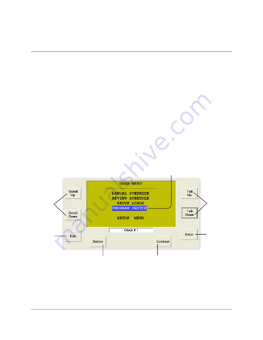
programming is done from the DTC Clock (shown 

below)/Programmer located in the master 

Lighting Control Panel (LCP) .
Virtual Clock or Unity Lighting Control software 

allows remote connection via the internet or 

modem to the DTC .

Use to 

position the 

cursor

Scroll 

through 

choices in  

one field

Exit out  

of a menu

Select an 

item or 

enter a 

sub-menu

Deletes programming or 

information about an item 

(use with caution)

Increases/decreases 

contrast of display screen

Cursor

Summary of Contents for GR 2400

Page 1: ...ting Time Schedules 8 Schedule Types Trigger Events 9 Control Types Group Types 10 Programming Groups 11 Important Note This programming guide covers the basics programming switches schedules and photosensors Other manuals exist for more advanced programming issues Call us if you have questions or need assistance during the programming of your system Technical Support 800 345 4448 ...

Page 2: ...es Additionally help is only a call away If equipped with a modem we can dial into your system and program it for you at no cost Call us any time at 800 345 4448 The DTC Digital Time Clock Most programming is done from the DTC Clock shown below Programmer located in the master Lighting Control Panel LCP Virtual Clock or Unity Lighting Control software allows remote connection via the internet or m...

Page 3: ...ct items within a field or to exit the field A field is a display in which one of many items can be selected In other words a value can be changed by selecting a new one SCROLL UP SCROLL DOWN TAB UP TAB DOWN MAINTAIN TOGGLE MIXED MODE OFF MODE ON MODE GROUP 1 TAB UP TAB DOWN ENTER SWITCHES PAGE 1 2 33 Reception 52 Master Sw 1 53 Master Sw 2 59 Master Sw 3 61 Hallway 100 61 Hallway 200 61 Hallway 2...

Page 4: ...ffice 101 52 Office 102 53 Office 103 59 Office 104 61 Office 105 61 Office 106 61 Office 107 SWITCHES PAGE 2 2 63 Reception 64 Photocell North 65 Photocell West 66 Master Sw 3 71 Hallway 100 72 Hallway 200 73 Hallway 220 SELECT BTN SW ID 63 SETUP PAGE 1 1 B1 BUTTON 1 B2 BUTTON 2 B3 BUTTON 3 B4 BUTTON 4 B5 BUTTON 5 B6 BUTTON 6 PROGRAMMING A DIGITAL SWITCH To Start 1 TAB to start 2 TAB to Program S...

Page 5: ...have navigated to the correct Button Trigger or Group and before you add or delete loads it is important to determine the Control Type 1 SCROLL to select Control Type 2 TAB down to LCP 1 For all Control Types except Mixed Mode 1 SCROLL to select LCP 1 2 3 etc 2 TAB to Load 1 3 SCROLL to load you want to add or delete 4 ENTER to select load it will appear in the Load Summary 5 ENTER again to delete...

Page 6: ...is like a digital switch 1 TAB to the correct Switch ID 2 ENTER to select To Select Trigger Each Photocell Card has 14 Triggers each of which may control its own set of loads may be programmed to switch loads on and off at levels analogous to foot candles 1 If needed SCROLL to the correct page for Triggers higher than T6 2 TAB to the correct Trigger 3 ENTER to select 4 SCROLL to Maintain 5 ENTER t...

Page 7: ... falls below 0030 Off when light level rises above 0031 SENSOR ID 64 1 Analog 1 0050 Time Delay TEST 5 Sec On when light level falls below 0030 Off when light level rises above 0040 BASIC PHOTOCELL SETTINGS cont d To Program a Trigger Level Photocell Cards come with one or three photocell inputs Any of those photocells may be used to control the Trigger 1 If Analog 1 is displayed SCROLL to select ...

Page 8: ... to start 2 TAB to REVIEW SCHEDULE 3 ENTER to select To Select the Schedule 1 SCROLL to the correct page 2 TAB to the correct Schedule 1 32 3 ENTER to select To Select a Holiday List This portion of the menu allows you to select from any pre existing Holiday Lists See below to edit the Holiday List 1 TAB to EXCEPT NONE 2 SCROLL to desired Holiday Exception if any 3 TAB to the correct Schedule 1 32...

Page 9: ... nearest second and allows a schedule to start and end on specific dates 1 Tab to desired day and ENTER to edit 2 TAB to the hour and SCROLL to select 3 TAB to minutes and SCROLL to select 4 TAB to seconds and SCROLL to select To link other days to this schedule 1 TAB to Every Day 2 SCROLL to desired days or day sets and ENTER to select 3 EXIT to edit more days To select schedule start and stop da...

Page 10: ...e GROUP is On the loads are On When the GROUP is Off any switch controlling any loads within the GROUP may only turn those loads On for a programmed time MAINTAIN BLINK Uses all of the features of the MAINTAIN TIMER and adds a blink warning prior to shutting loads off Control Types Control Types describes how loads are controlled TOGGLE Toggle up to 8 loads On or Off ON MODE Up to 8 loads On only ...

Page 11: ...To Access the Group Within the DTC there are two paths you can use to access a group for programming purposes A From USER MENU 1 TAB to start 2 TAB to GROUP LOADS 3 ENTER to select B From the SCHEDULE MENU 1 EXIT schedule when complete 2 TAB to NO LOADS 3 ENTER to select 1 SCROLL to select Group Type see page 10 for selecting group types 2 Add or delete loads see page 5 for adding or deleting load...

Page 12: ... 2007 2009 2010 Acuity Brands Lighting Inc All Rights Reserved Form No 1382 017 994 004 0022 Lighting Control Design 9144 Deering Ave Chatsworth CA 91311 www lightingcontrols com ...

Reviews: