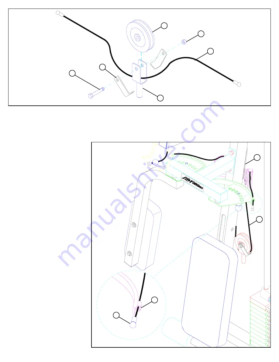
STEP 29:
25
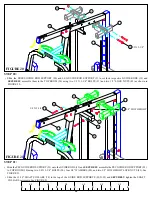
FIGURE 29
• Assemble one 4-1/2” PULLEY (48) around the PEC DEC CABLE (46) and to the PULLEY BRACKET (26) using one 3/8 X 2” BOLT (89),
two 2-7/8 X 1” CABLE CLIPS (67) and one 3/8” LOCKNUT (82) as shown in FIGURE 29.
STEP 30:
FIGURE 30
3/8 X 2” 89
48
46 PEC CABLE
82
• Slide the ends of the PEC DEC CABLE
(46) into the bushings on the PEC CAMS
(28) as shown on FIGURE 30.
• Lay the PEC DEC CABLE (46) over the
pulleys and under the cable retaining clips
in the CENTER PULLEY BRACKET (27)
as shown in FIGURE 30.
(NOTE: Securely
tighten the pulley connections in the
CENTER PULLEY BRACKET (27).
The cable retaining clips should be at ap-
proximately a 45°
angle.)
46
46
28
27
PEC
CABLE
26
67


