General Information
Control Panel
1
0
2
3
4
14
WATER
WATER
TEMP
TEMP
OPER
OPER
HEATING
HEATING
MODE
MODE
ڸ
ۀ
ڿ
ھ
ڽ
ہ
ڹ
ں
ڻ
ڼ
ۂ
ۃ
ۄ
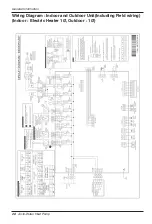
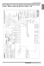
Wiring Diagram : Indoor Unit
- Refer to the wiring diagram inside the control box.
Circuit Diagram : Indoor Unit
- Refer to the circuit diagram inside the front panel.
Wiring Diagram : Outdoor Unit
- Refer to the attached wiring diagram in the outdoor unit.
Installation Manual
27
ENGLISH
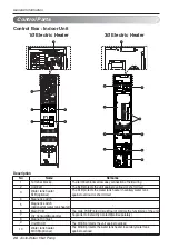
No Name
1
Display
2
Change Temperature Button
3
Water Heating Enable / Disable Button
4
Power Button
5
Operation Mode Selection Button
6
Silent Mode On / Off Button
7
Temperature Setting Mode Button
8
Temperature View Mode Button
9
Function Setting Button
10
Programming Button
11
Direction Button (Up, Down, Left, Right)
12
Set / Clear button
13
ESC Button
14
Pressure gage
Summary of Contents for Therma V AHUW096A2
Page 97: ......

